Plastic ferrule

Inactive Publication Date: 2005-04-12
FUJITSU COMPONENENT LTD
View PDF10 Cites 18 Cited by
  • Summary
  • Abstract
  • Description
  • Claims
  • Application Information

AI Technical Summary

Benefits of technology

It is therefore an object of the present invention to provide a plastic ferrule usable in an optical connector, wherein molding dimensional precision in high level can be attained relatively e

Problems solved by technology

With this process, however, there has been conventionally a problem as to how to improve dimensional precision and mechanical strength of a molded product up to a level at which there is no practical problem.
However, in the construction of a conventional plastic ferrule, the thickness of a cylindrical wall of the centering section changes unavoidably from the uncoated-fiber holding bore of a small diameter to the coated-fiber holding bore of a larger diameter.
This wall thickness change may cause unbalanced mold shrinkage of resinous material of the ferru

Method used


Image

  • Plastic ferrule
  • Plastic ferrule
  • Plastic ferrule

Examples


first embodiment

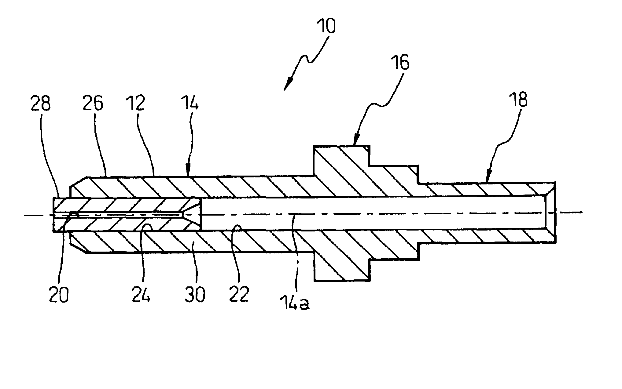
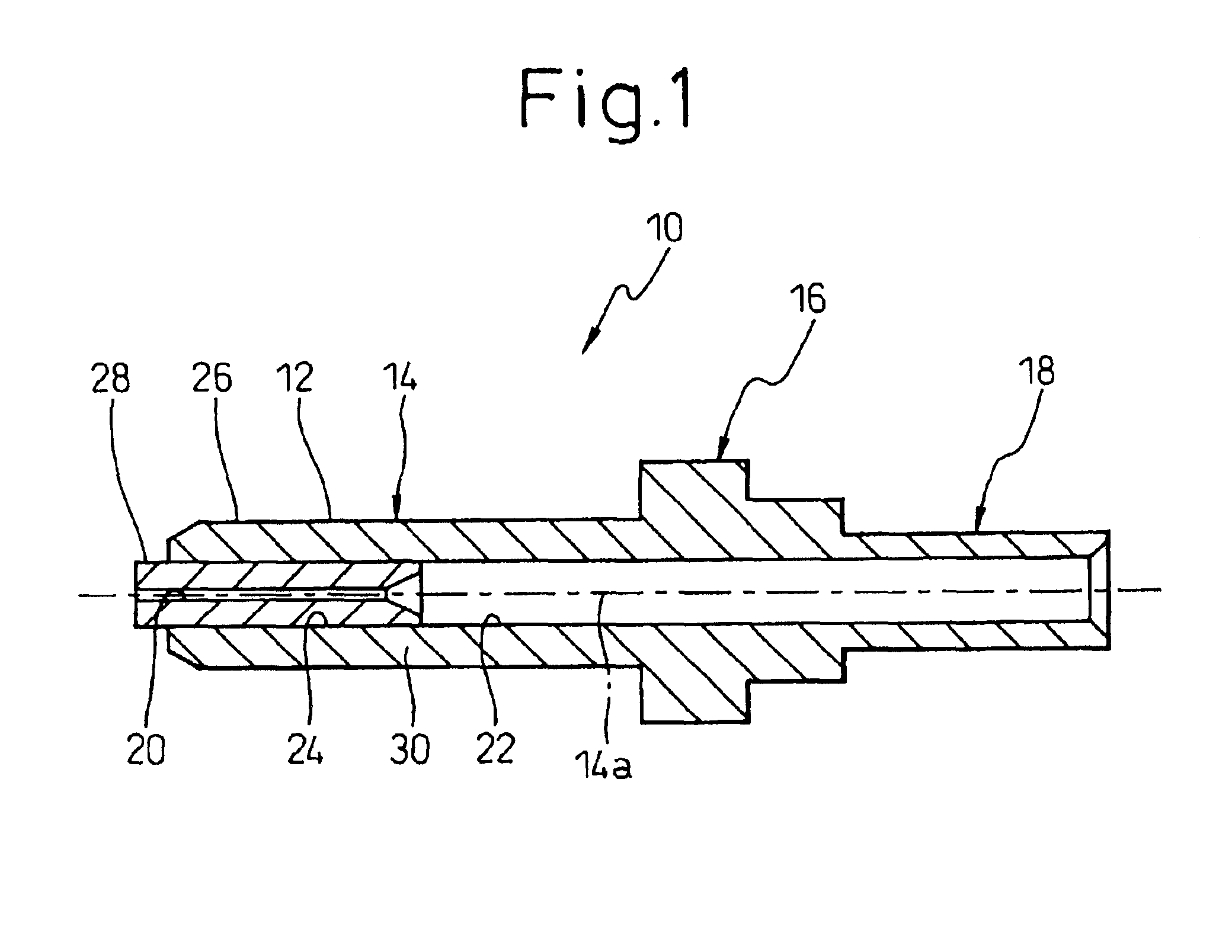
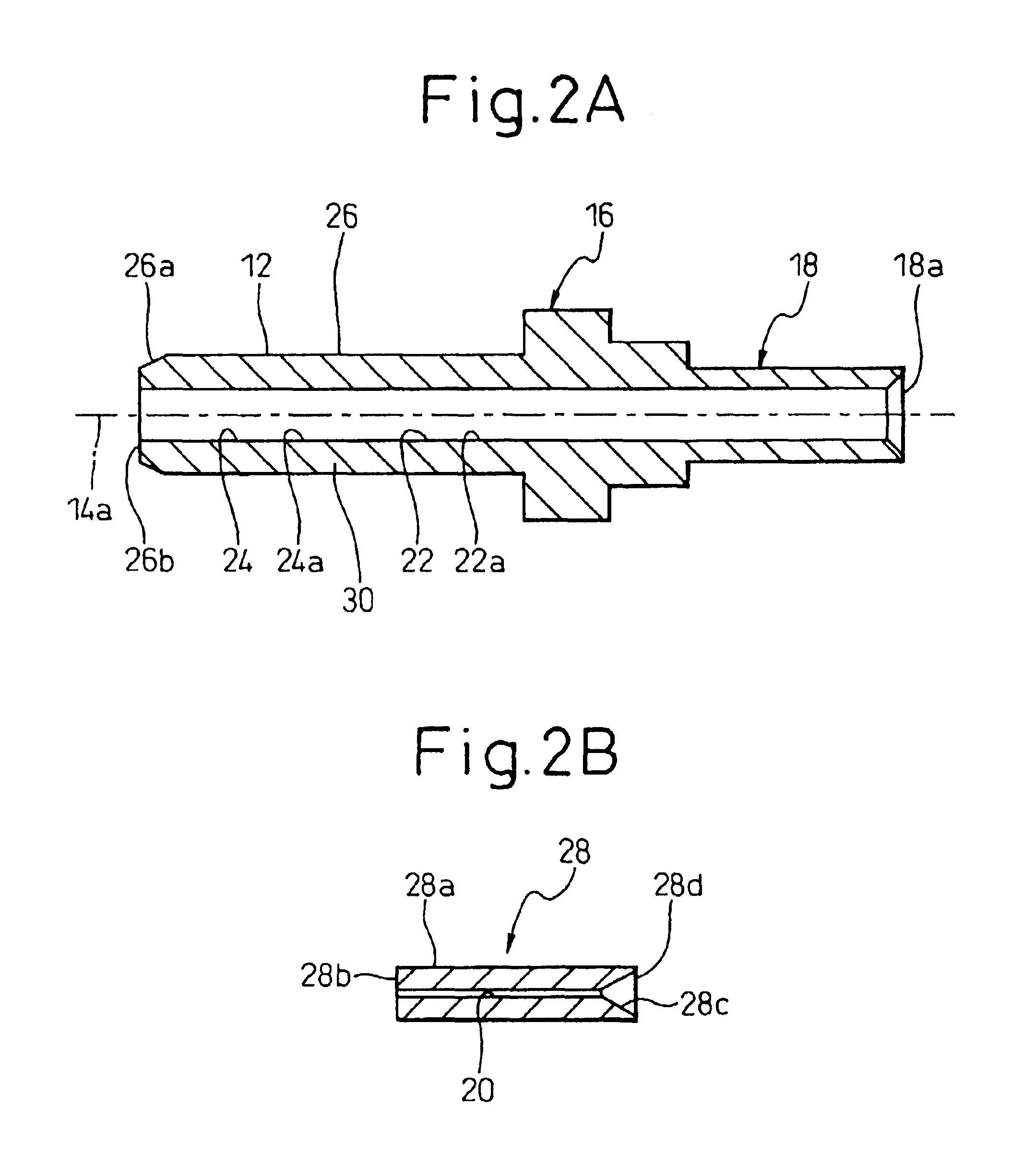
Referring now to the drawings, in which the same or similar components are denoted by common reference numerals, FIGS. 1 to 3 show a plastic ferrule 10, according to the present invention, FIG. 4 shows a connected condition of optical fibers in which the ferrule 10 is used, and FIGS. 5 and 6 respectively show modifications of the ferrule 10.

The ferrule 10 includes a hollow tubular centering section 14 having a cylindrical outer circumferential surface 12, a flange section 16 provided adjacent to one axial end (or a proximal end) of the centering section 14 so as to project radially outwards, and a guide section 18 extending opposite to and concentric with the centering section 14 from the flange section 16. The centering section 14 is provided, along a center axis 14a thereof (that is, the center axis of the cylindrical outer circumferential surface 12), with a first, uncoated-fiber holding bore 20 for securely accommodating an uncoated optical fiber with no coating, and a second, c...

second embodiment

FIGS. 7 and 8 show a plastic ferrule 50 according to the present invention. The ferrule 50 employs a measure, different from that in the ferrule 10, for relatively easily ensuring high dimensional precision for molding in the centering section.

The ferrule 50 includes a hollow tubular centering section 54 having a cylindrical outer circumferential surface 52, a flange section 56 provided adjacent to one axial end (or a proximal end) of the centering section 54 to project radially outwards, and a guide section 58 extending opposite to and concentric with the centering section 54 from the flange section 56. The centering section 54, the flange section 56 and the guide section 58 are integrally formed into a unitary body from desired resinous material such as liquid crystal polymer by, e.g., an injection molding process.

The centering section 54 is provided, along the center axis 54a thereof (that is, the center axis of the cylindrical outer circumferential surface 52), with an uncoated-...

third embodiment

FIGS. 10A and 10B show a plastic ferrule 70 according to the present invention, which is molded through such a two-color molding method. The ferrule 70 is comprised of a centering section 74 having a cylindrical outer circumferential surface 72, a flange section 76 provided adjacent to one axial end (or a proximal end) of the centering section 74 so as to project radially outwards, and a guide section 78 extending opposite to and concentric with the centering section 74 from the flange section 76. The centering section 74 is provided, along the center axis 74a thereof (that is, the center axis of the cylindrical outer circumferential surface 72), with a first, uncoated-fiber holding bore 80 for securely accommodating an uncoated optical fiber F (FIG. 4), and a second, coated-fiber holding bore 82 having a larger diameter than the uncoated-fiber holding bore 80, for securely accommodating a coated optical fiber C (FIG. 4), formed in communication with each other in axial direction.

Th...


PUM

PropertyMeasurementUnit
Diameteraaaaaaaaaa
Lengthaaaaaaaaaa
Hardnessaaaaaaaaaa

Abstract

A plastic ferrule including a centering section having a tubular body. The tubular body is provided with an outer-circumferential centering reference surface and a center axis of the centering reference surface. The centering section includes a resinous outer tube part having the outer-circumferential centering reference surface and provided, along the center axis, with a coated-fiber holding bore for securely accommodating a coated optical fiber and a fixing bore extending from the coated-fiber holding bore, the outer tube part forming a tubular wall with a generally uniform thickness as a whole. The centering section also includes an inner tube part fixed to the fixing bore of the outer tube part and provided along the center axis with an uncoated-fiber holding bore, communicating with the coated-fiber holding bore, for securely accommodating an uncoated optical fiber.

Description

BACKGROUND OF THE INVENTION1. Field of the InventionThe present invention relates to a plastic ferrule capable of being used in an optical connector. The present invention further relates to a method of manufacturing a plastic ferrule, and also to a mold capable of being used in the manufacturing method.2. Description of the Related ArtIn recent years, in the field of optical connectors, a plastic ferrule has been developed, which is integrally molded in one piece from a resinous material, in view of promoting mass production and cost reduction. Conventionally, a plastic ferrule is comprised of a cylindrical centering section which has an uncoated optical fiber exposing port at one axial end face thereof, and a flange section projecting radially outward adjacent to the proximal end of the centering section. The centering section is provided, along its center axis, with an uncoated-fiber holding bore which opens to the fiber exposing port for securely accommodating an uncoated optica...

Claims


Application Information

Patent Timeline
IPC IPC(8): B29C45/16G02B6/38G02B6/36B29C45/14B29C45/36B29K105/20B29L11/00B29L31/36
CPCB29C45/16B29C45/1615G02B6/3835G02B6/3865B29C45/1676Y10T16/39B29L2011/0075
Inventor TAKAHASHI, EIETSUNOMURA, KAZUOYAMAMOTO, SUSUMUMATSUMIYA, HIROSHIDAIKUHARA, OSAMUKAWAGUCHI, SHINICHIROSHIMIZU, NOBORUMIYAZAWA, HIDEOWATANABE, KOJITSUGANE, HIROHIKOIKEMORI, NAOKI
Owner FUJITSU COMPONENENT LTD
Why Eureka
Try Eureka