Rough- and finish-grinding of a crankshaft in one set-up

Inactive Publication Date: 2005-04-12
ERWIN JUNKER MASCHNINENFAB
View PDF13 Cites 45 Cited by
  • Summary
  • Abstract
  • Description
  • Claims
  • Application Information

AI Technical Summary

Benefits of technology

The object of the invention is to develop a method of grinding crankshafts and an apparatus with which di

Problems solved by technology

With these crankshafts, given a previous heat treatment, there is a particularly high risk of the crankshaf

Method used


Image

  • Rough- and finish-grinding of a crankshaft in one set-up
  • Rough- and finish-grinding of a crankshaft in one set-up
  • Rough- and finish-grinding of a crankshaft in one set-up

Examples


Example

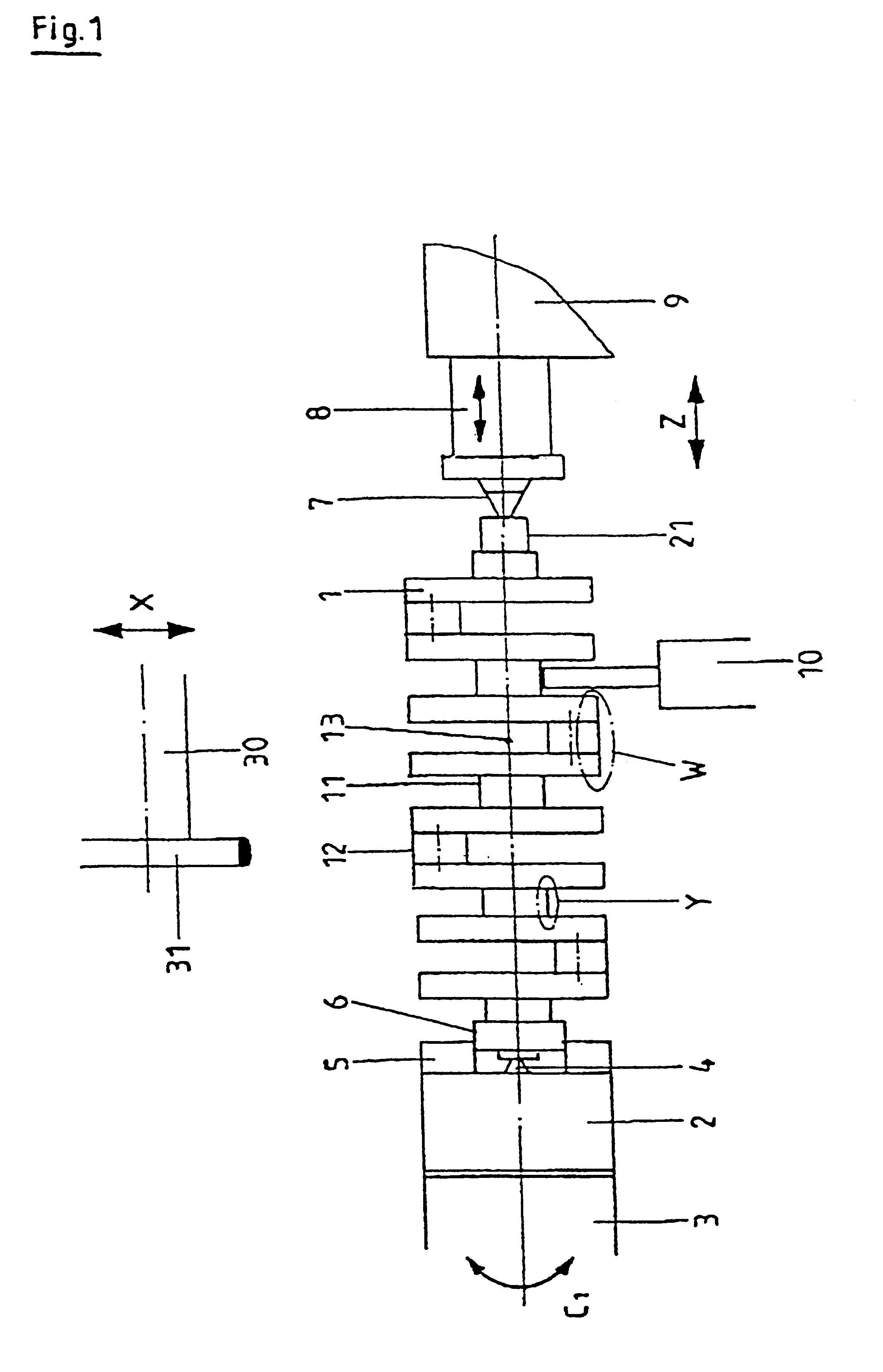
FIG. 1 shows a representation of a clamped crankshaft 1. This crankshaft 1 is clamped in a chuck 2 which is flange-mounted on a work spindle 3 of a work headstock (not shown in any more detail). Located in the center of the chuck 2 is a first center 4 on which the crankshaft 1 is concentrically oriented. The crankshaft 1 is radially driven by chuck jaws 5 of the chuck 2 which grip an outer periphery of a flange 6 of the crankshaft 1. Another shaft end of the crankshaft 1 is supported by a second center 7 of a tailstock 9. The second center 7 of the tailstock 9 is mounted on an axially displaceable quill 8.

Instead of being equipped with a second center 7, the tailstock 9 may also be equipped with a further chuck, as at the work headstock, although this is not shown here. The chuck jaws of this chuck then grip a journal end 21 of the crankshaft 1.

The crankshaft 1 may be clamped under slight pressure, in a pressureless manner or even under axial tension. According to the embodiment sho...


PUM


Abstract

Method of grinding a concentrically clamped crankshaft, a crankshaft grinding machine for carrying out the method, and a crankshaft of high-alloy steel or cast material. The method provides for pin journals and main journals of the crankshaft to be ground in one set-up such that first, at least the main journals are rough-ground and then the pin journals are finish-ground and after that the main journals are finish-ground. The crankshaft grinding machine forms a machining center by means of which corresponding rough-grinding and finish-grinding is possible in a single set-up.

Description

FIELD OF THE INVENTIONThe present invention relates to a method of grinding a concentrically clamped crankshaft and to a crankshaft grinding machine for carrying out the method.BACKGROUND OF THE INVENTIONIn known methods, crankshafts are ground in a plurality of steps on different machines in a plurality of operations on grinding machines specifically equipped for this purpose.Another method and a corresponding apparatus have been disclosed in DE 43 27 807. In this publication, a crankshaft is clamped with axial tension between locating centers of a work headstock and tailstock of a grinding machine. In this set-up, all the bearings, pin journals, flanges, journals and end faces of the crankshaft are finish-ground. In this case, at least two appropriately contoured grinding wheels are used.It is thus known from the prior art that, on one hand, the crankshaft is produced in a plurality of machining steps on a plurality of grinding machines or is finish-ground in one set-up.OBJECTS AN...

Claims


Application Information

Patent Timeline
IPC IPC(8): B24B5/00B24B5/42B24B41/06B24B1/00B24B27/00B24B51/00
CPCB24B5/42
Inventor JUNKER, ERWIN
Owner ERWIN JUNKER MASCHNINENFAB
Why Eureka
Try Eureka