Protective device for a hand machine tool

Inactive Publication Date: 2005-04-12
ROBERT BOSCH GMBH
View PDF13 Cites 37 Cited by
  • Summary
  • Abstract
  • Description
  • Claims
  • Application Information

AI Technical Summary

Benefits of technology

If the glide shoe constricts the cross section of the exit region in the region of the dust removal tube, it is more difficult for air to escape out of the protective cover. Excess pressure forms inside the protective cover that presses the air containing particles or dust toward the dust removal tube.
Advantageously, an air inlet opening remains in the protective cover or between the protective cover and the work piece, the size of which is independent of the depth of penetration of the tool in the work piece. In this fashion, a constant flow of air—that is independent of the depth of penetration of the tool in the work piece—from the air inlet opening into a dust removal tube, and, therefore, constant dust removal, is made possible.
When the air inlet opening is located opposite from the dust removal tube relative to the tool, an air stream directed toward the dust removal tube is obtained that facilitates entry of dust into the dust removal tube.
The blow-off effect of the sanding dust is further improved by means of a damping plate located inside the protective cover, since the air whirled by the rotating sanding disk backs up there, and the air stream is directed out to the dust removal tube. The damping plate can be located on the side opposite from the

Problems solved by technology

Guard devices for power tools, in particular for angle grinders, are known, the protective covers of which offer a certain level of protection during sanding work, but do not support sufficient dust removal

Method used


Image

  • Protective device for a hand machine tool
  • Protective device for a hand machine tool
  • Protective device for a hand machine tool

Examples


Embodiment Construction

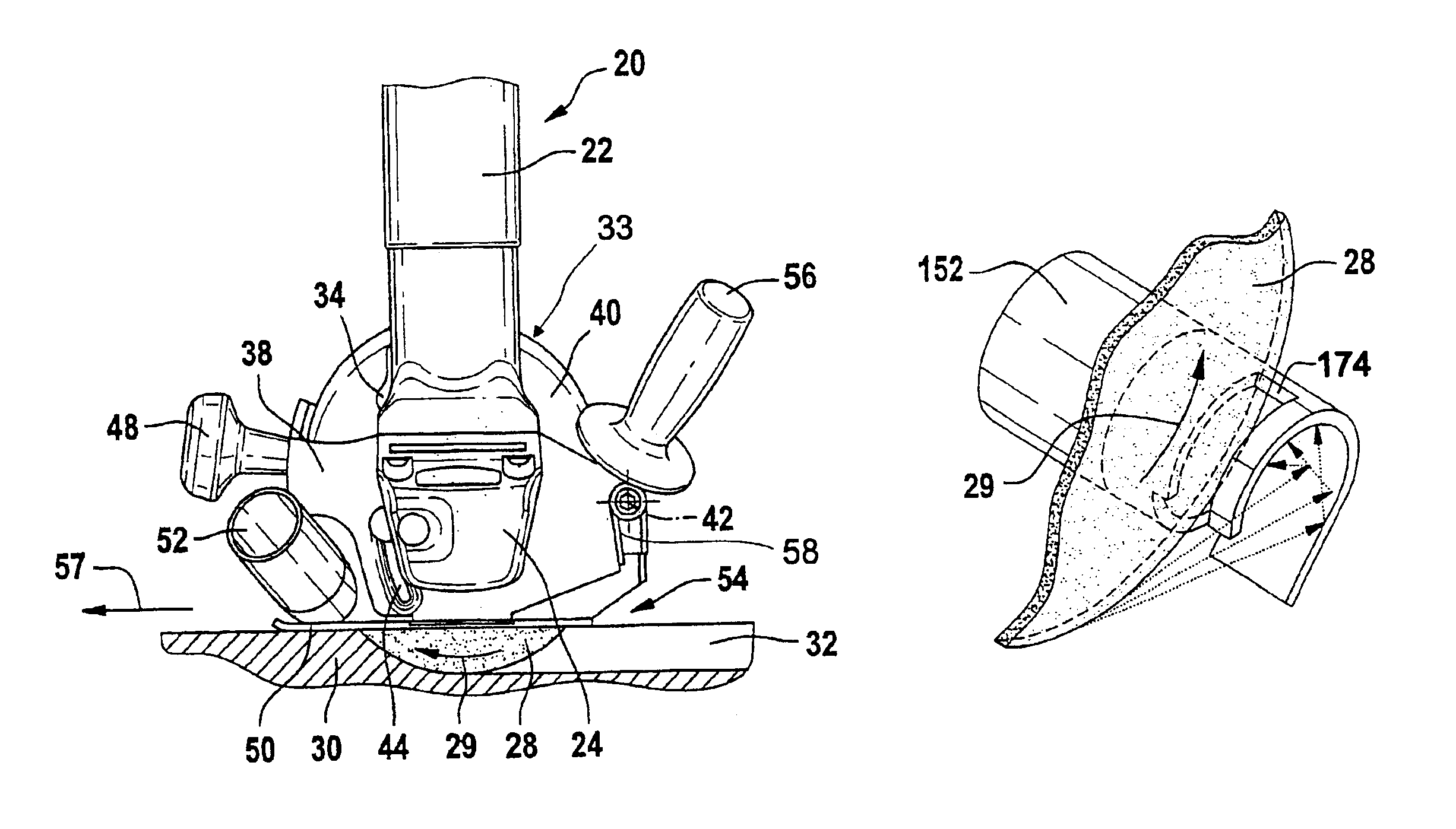
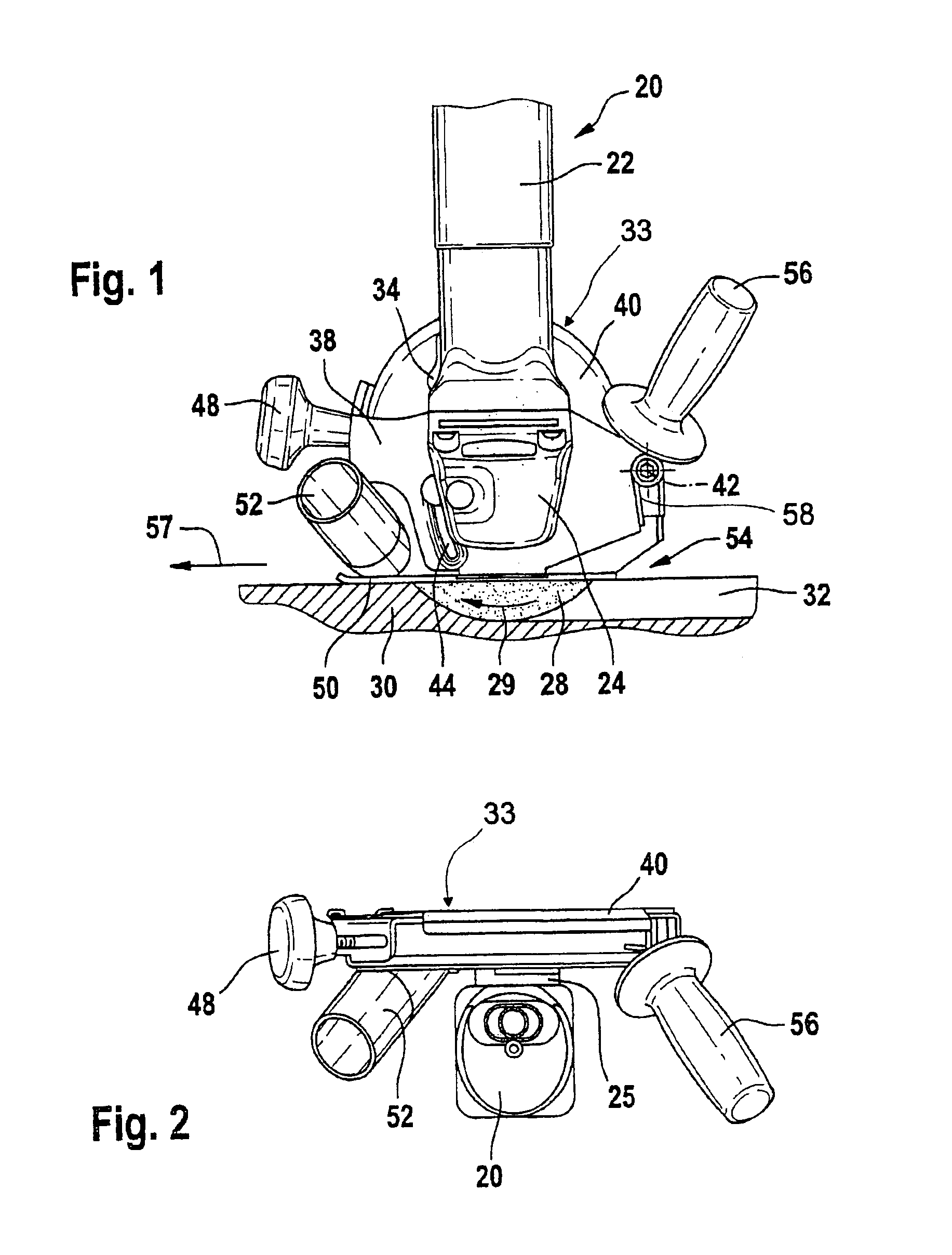
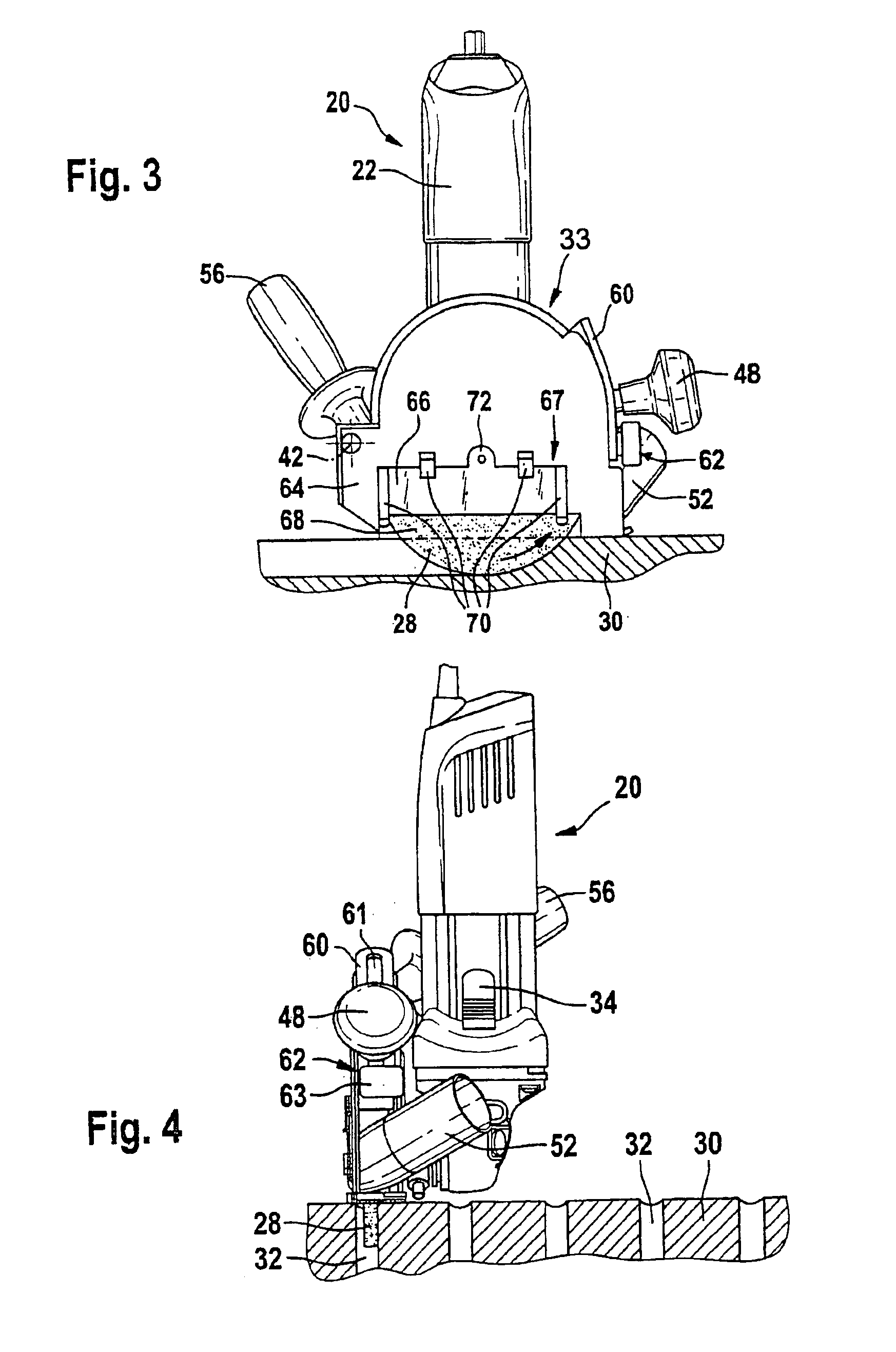
FIG. 1 is the side view of an angle grinder 20, the motor housing 22 of which extends substantially upward at a right angle and contains a not-shown motor.

As viewed downward at a right angle, a gearbox housing 24 adjoins the motor housing 22, the drive shaft 26 (FIG. 13) of which said gearbox housing extends at a right angle to the plane of the drawing and carries a tool on its exposed end. The tool is a sanding disk 28. It rotates in the direction of rotation 29 in a clockwise direction and plunges into a work piece 30, in which it cuts a groove 32 coming from the right.

As shown on the left side, a sliding button 34 of an on-and-off switch is attached to the motor housing 22.

A guard device 33 is fastened to the angle grinder 20. It comprises a fastening device and a protective cover 40. The fastening device is designed as a swivelling arm 38. The swivelling arm 38 is fastened via a well-fitting mounting opening 36 (FIG. 18) to a cylindrically designed, axial extension of the gearbo...


PUM

PropertyMeasurementUnit
Angleaaaaaaaaaa
Sizeaaaaaaaaaa
Depthaaaaaaaaaa

Abstract

The invention is based on a guard device (33) for a power tool, in particular for a sanding power tool, having a protective cover (40) that is provided to at least partially encompass a disk-shaped, rotating tool, and having a dust removal tube (52), the longitudinal axis of which is located at an angle of up to 80° to the axis of rotation of the tool.
It is proposed that part of the dust removal tube (52) passes through the plane of a flat side of the tool.

Description

BACKGROUND OF THE INVENTIONThe invention is based on a guard device for a power tool, in particular for a sanding power tool.Guard devices for power tools, in particular for angle grinders, are known, the protective covers of which offer a certain level of protection during sanding work, but do not support sufficient dust removal despite the powerful external vacuum cleaners typically used. Additionally, the typical, radial routing of the suction tube makes handling the power tool difficult because the suction tube protrudes radially.SUMMARY OF THE INVENTIONThe invention is based on a guard device for a power tool, in particular for a sanding power tool, having a protective cover that is provided to at least partially encompass a disk-shaped, rotating tool, and having a dust removal tube, the longitudinal axis of which is located at an angle of up to 80° to the axis of rotation of the tool.It is proposed that part of the dust removal tube passes through the plane of a flat side of t...

Claims


Application Information

Patent Timeline
IPC IPC(8): B23Q11/00B24B23/02B24B23/00B24B55/05B24B55/00
CPCB23Q11/0046B24B55/052B24B23/028Y10T83/7734
Inventor WENDT, DIETERVOIGT, MIKEKLEIDER, ALBERTSCHADOW, JOACHIMNEEF, KURTMUELLER-BOYSEN, ULRICH
Owner ROBERT BOSCH GMBH
Why Eureka
Try Eureka