In-mold foam molded articles
- Summary
- Abstract
- Description
- Claims
- Application Information
AI Technical Summary
Benefits of technology
Problems solved by technology
Method used
Image

Examples
second embodiment
[0125]FIG. 15 is a perspective view of an automobile bumper core pertaining to a second embodiment;
[0126]FIG. 16 is a sectional view taken along line S2—S2 in FIG. 15;
[0127]FIG. 17 is a longitudinal sectional view of an in-mold foam molding apparatus pertaining to a second embodiment;
[0128]FIG. 18 is a sectional view taken along lines S3—S3 in FIG. 17;
[0129]FIG. 19 is a illustrative diagram of partitioning means;
[0130]FIG. 20 is a perspective view of a partitioning member;
[0131]FIG. 21 is a illustrative diagram of partitioning means of another design;
[0132]FIG. 22 is an illustrative diagram of partitioning means of yet another design.
[0133]FIG.23(a) is a perspective view of yet another core design and FIG. 23(b) is an illustrative diagram of a molding apparatus for molding the core;
[0134]FIG. 24(a) is a perspective view of yet another core design and FIG. 24(b) is an illustrative diagram of a molding apparatus for molding the core;
[0135]FIG. 25 is a longitudinal sectional view of a ...
third embodiment
[0136]FIG. 26 is an overall view of an in-mold foam molding apparatus pertaining to a third embodiment;
[0137]FIG. 27 is a sectional view taken along line S4—S4 in FIG. 26;
[0138]FIG. 28 is an overall view of an in-mold foam molding apparatus of another design;
[0139]FIG. 29 is an overall view of an in-mold foam molding apparatus of another design;
[0140]FIG. 30 is a sectional view taken along line S6—S6 in FIG. 29;
[0141]FIG. 31 is a illustrative diagram of an in-mold foam molding apparatus of another design;
[0142]FIG.32 is a perspective view of an automobile bumper core;
[0143]FIG. 33 is a sectional view taken along line S5—S5 in FIG. 26;
[0144]FIGS. 34(a) and 34(b) are an illustrative diagram of molding surface properties and internal rate of fusion;
[0145]FIG. 35 is an overall view of an in-mold foam molding apparatus of the conventional art;
[0146]FIG. 36 is a longitudinal sectional view of a section of a conventional mold containing air orifices;
[0147]FIG. 37 are plan views of a core v...
first embodiment
[0151]This first embodiment relates to an in-mold foam molding apparatus of the first type, equipped with moveable partitioning members, and to an in-mold foam molding method and molded article.
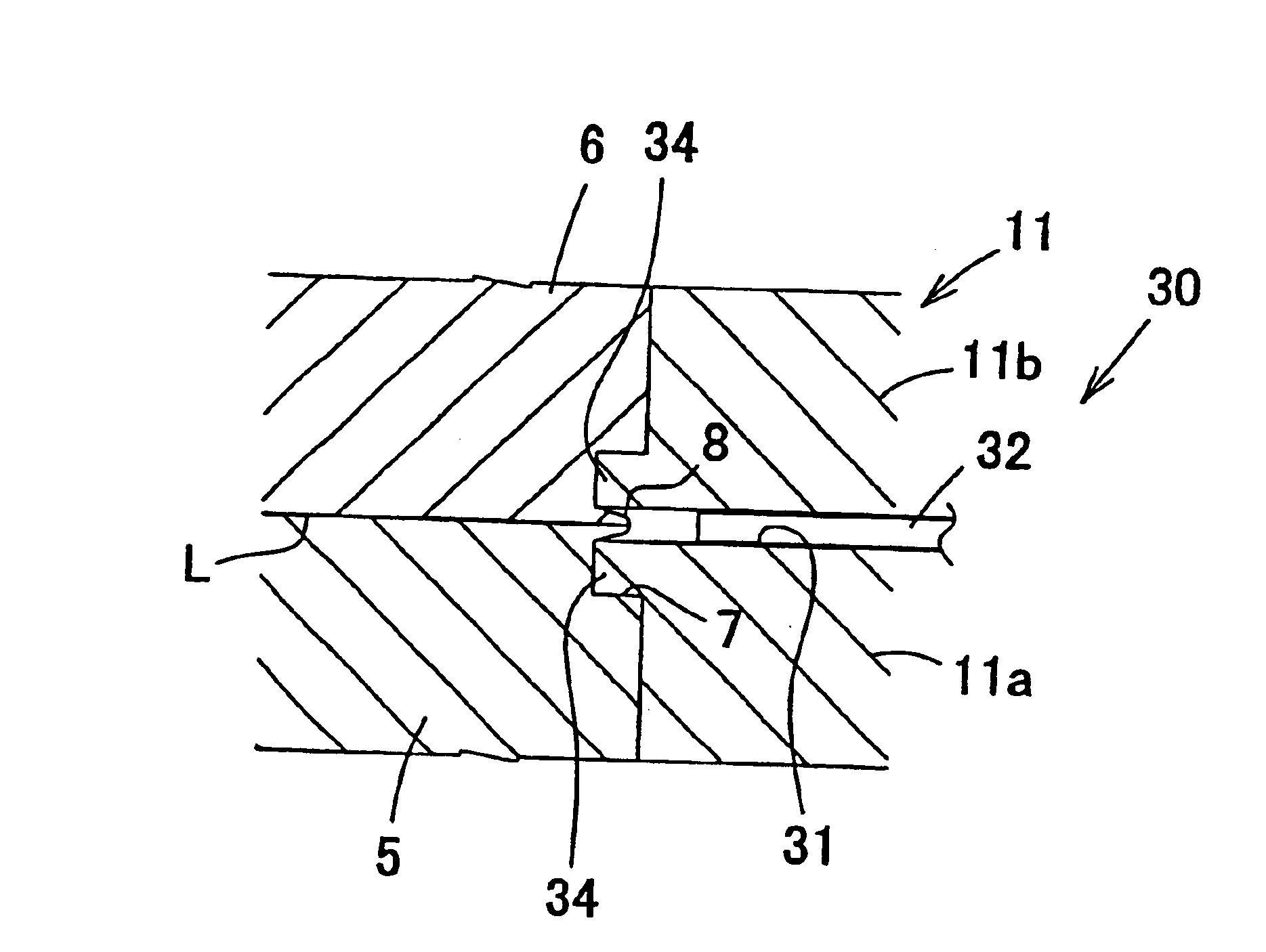
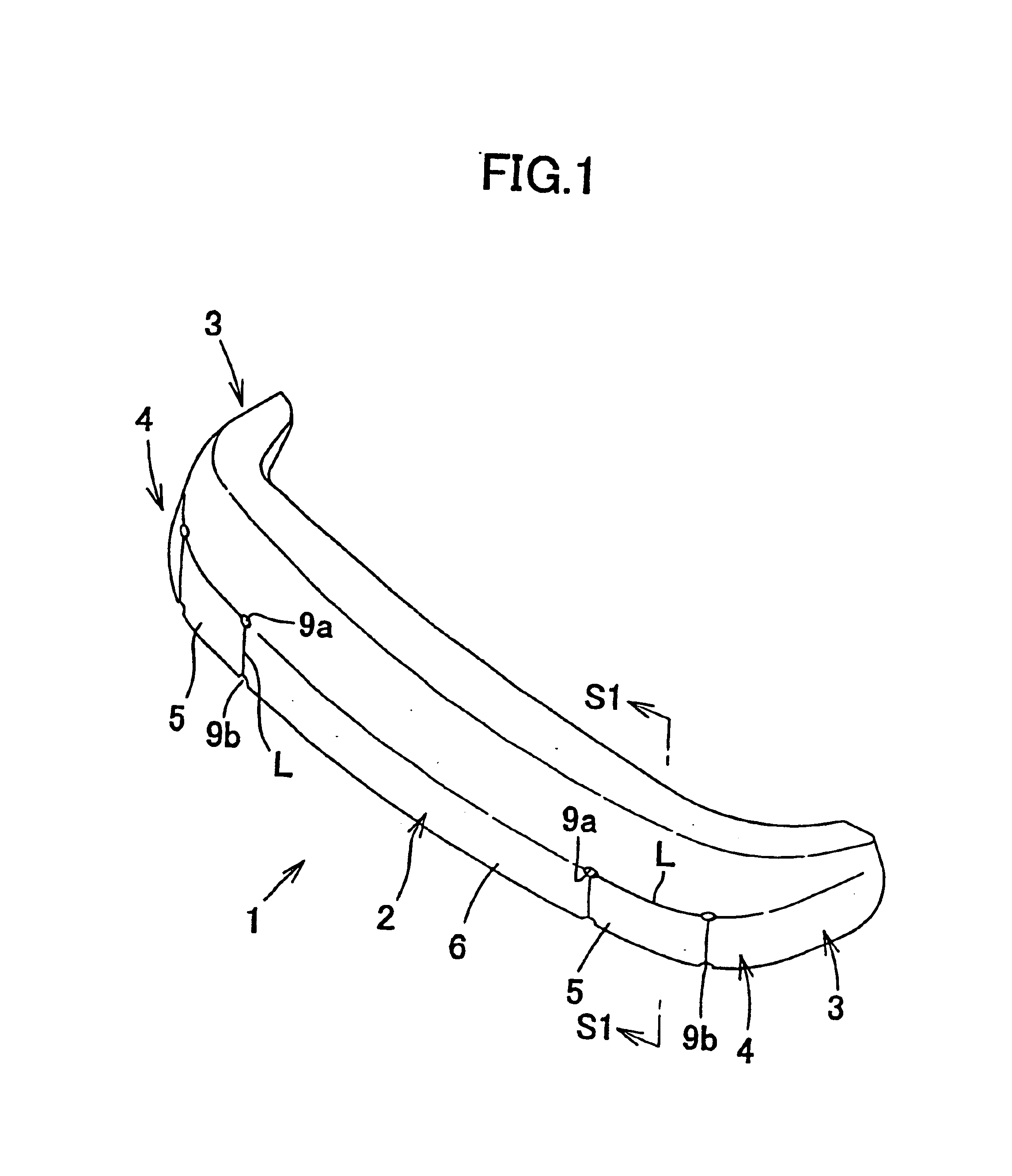
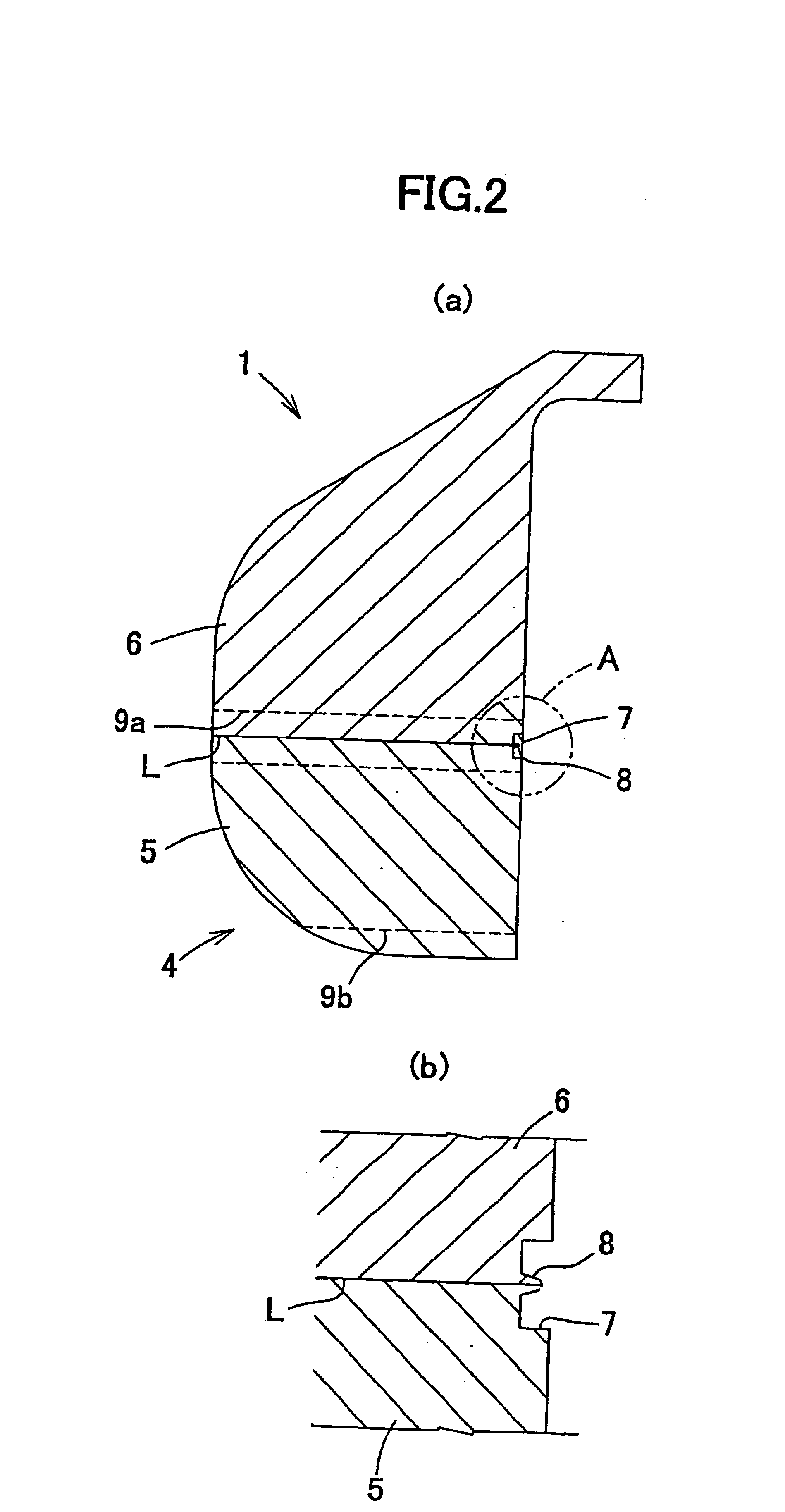
[0152]A core for an automobile bumper consisting of an in-mold foam molded article is first described. Referring to FIGS. 1 and 2, a core 1 has a front impact absorbing portion 2 that curves gently backward at the two ends thereof, and side impact absorbing portions 3 that extend backward from the two ends of front impact absorbing portion 2. At the bottom half of each corner portion 4 extending from impact absorbing portion 2 to a side impact absorbing portion 3 is formed a low expansion portion 5 comprising bead starting materials with a low degree of expansion, the remaining portions being composed of a high expansion portion 6 comprising bead starting materials with a higher degree of expansion than low expansion portion 5.
[0153]The central portion of front impact absorbing portion 2 is f...
PUM
| Property | Measurement | Unit |
|---|---|---|
| Expansion enthalpy | aaaaa | aaaaa |
Abstract
Description
Claims
Application Information
 - Generate Ideas
- Intellectual Property
- Life Sciences
- Materials
- Tech Scout
- Unparalleled Data Quality
- Higher Quality Content
- 60% Fewer Hallucinations
Browse by: Latest US Patents, China's latest patents, Technical Efficacy Thesaurus, Application Domain, Technology Topic, Popular Technical Reports.
© 2025 PatSnap. All rights reserved.Legal|Privacy policy|Modern Slavery Act Transparency Statement|Sitemap|About US| Contact US: help@patsnap.com