Transformer

a transformer and transformer technology, applied in transformers/inductance details, coils, inductances, etc., can solve the problems of increased copper losses, reduced and increased copper losses, so as to reduce the copper loss caused by the skin effect and improve the electromagnetic coupling conditions in the windings

Inactive Publication Date: 2005-04-12
KOITO MFG CO LTD
View PDF14 Cites 56 Cited by
  • Summary
  • Abstract
  • Description
  • Claims
  • Application Information

AI Technical Summary

Benefits of technology

When such a flat type wire is employed, a copper loss caused by the skin effect can be reduced. Also, because the toroidal-shaped portion is formed by winding this flat type wire in the overlapping manner, where both the respective windings and the respective cores are arranged along the overlapping direction of the flat type wire, the electromagnetic coupling conditions in the windings can be improved.

Problems solved by technology

When circular wires are employed as windings (coils), a skin effect caused by high-frequency currents may present a problem.
That is, copper losses can increased and electromagnetic coupling conditions can degrade with the circular wire windings.
For a circular wire, copper losses may increase because an effective volume of high-frequency current may not be sufficiently secured as compared to a volume of a winding of this circular wire.
If a circular type wire is used in such a transformer, an electromagnetic coupling characteristic between a primary winding (primary coil) and a secondary winding (secondary coil) would deteriorate because of air gaps between the sandwich windings.

Method used


Image

  • Transformer
  • Transformer
  • Transformer

Examples


Embodiment Construction

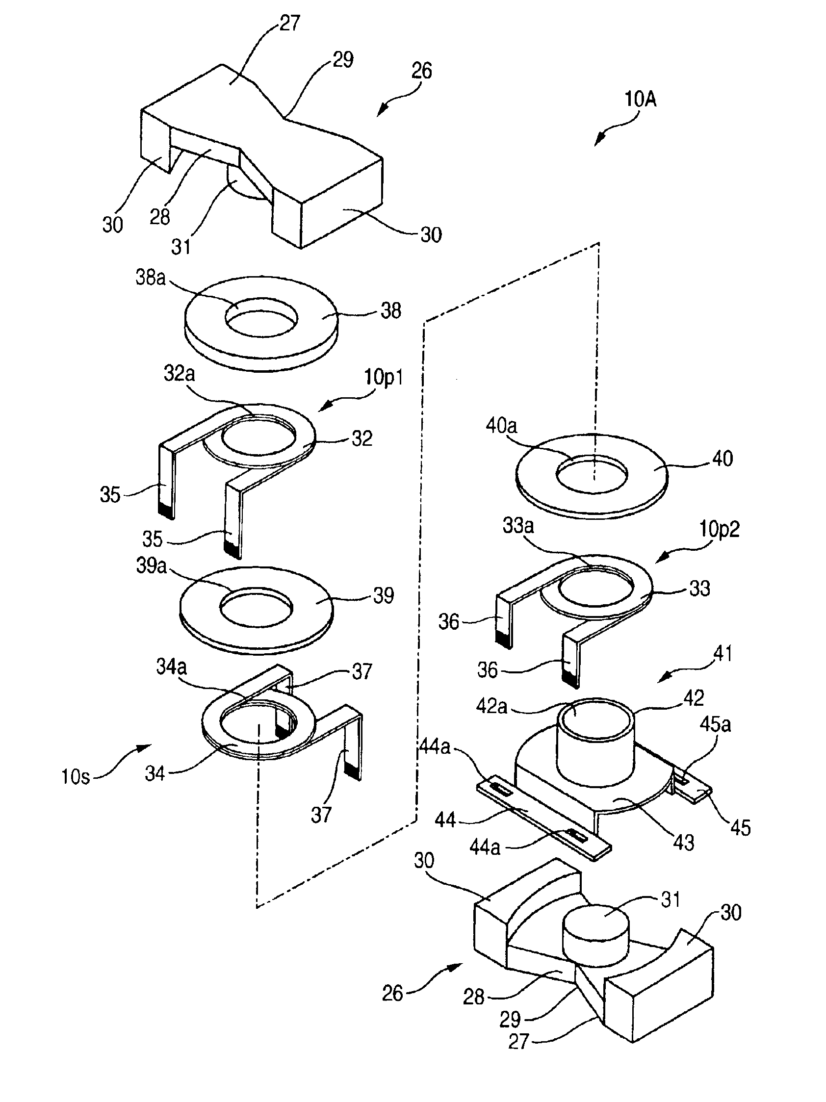
The present invention is related to a transformer equipped with a coil unit containing a plurality of coils (windings), and a plurality of cores. The coil unit is sandwiched by the plural cores. The transformer has a structure suitable for high-frequency. An exemplary use of this transformer as applied to an ignition circuit of a discharge lamp will be described below.

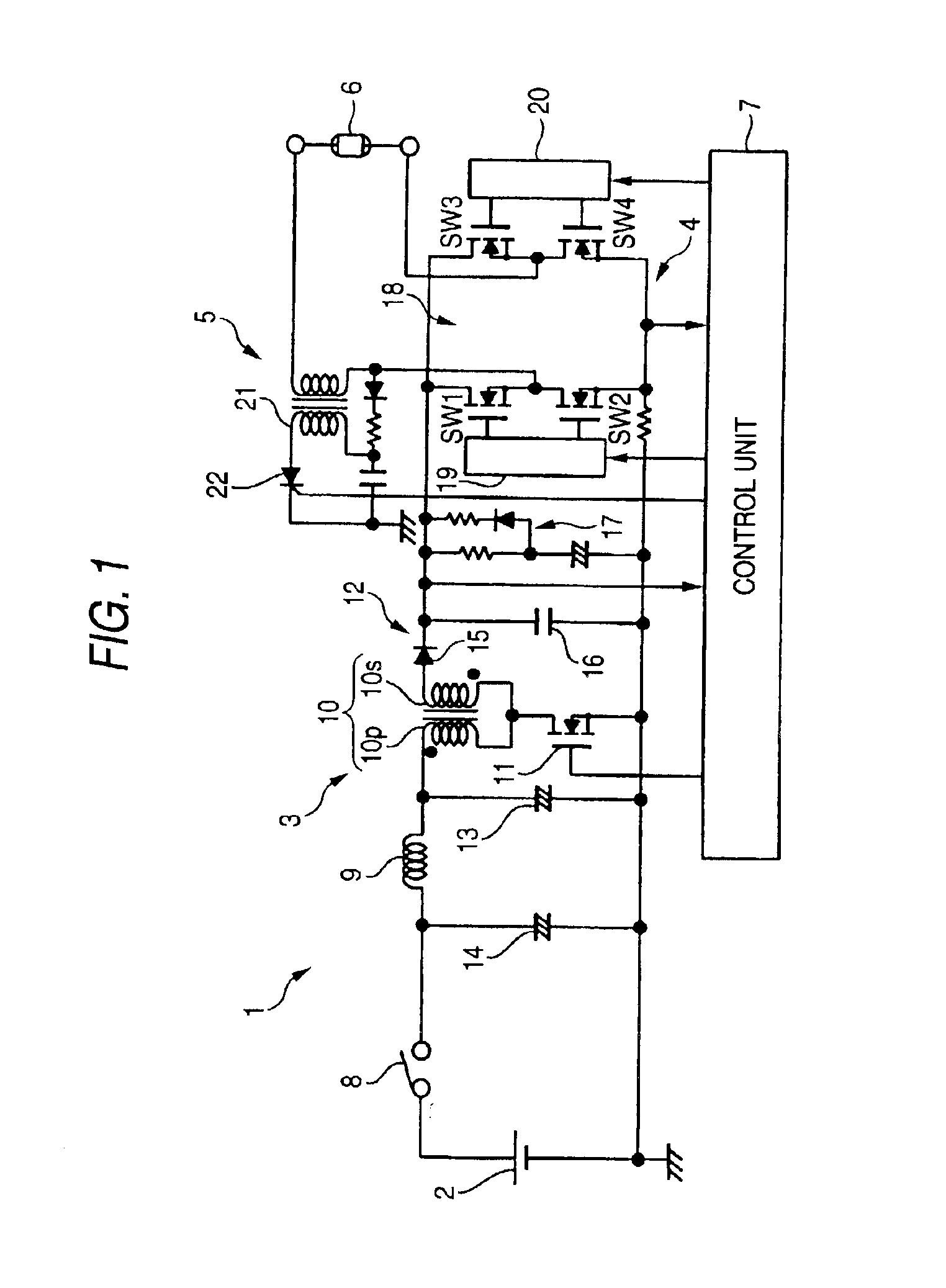
FIG. 1 represents a structural example of a discharge lamp ignition circuit.

A discharge lamp ignition circuit 1 is provided with a DC power supply 2, a DC-to-DC converting circuit 3, a DC-to-AC converting circuit 4, a starting circuit 5, and a control unit 7 for controlling ON / OFF operations of a discharge lamp 6.

The DC-to-DC converting circuit 3 receives an input voltage from the DC power supply 2, and then, converts this received DC voltage into a desirable DC voltage. In this example, a flyback type DC-to-DC converter can be employed as the DC-to-DC converting circuit 3.

In other words, the DC input voltage which is ...


PUM

PropertyMeasurementUnit
thicknessaaaaaaaaaa
thicknessaaaaaaaaaa
angleaaaaaaaaaa

Abstract

A transformer is provided with a coil portion containing primary windings and a secondary winding. Cores sandwich the coil portion. Each of these windings includes a toroidal-shaped portion that is formed by winding flat type wires in a toroidal shape and by overlapping these flat type wires. Edge portions of this flat type wire are derived from the toroidal-shaped portion respectively. A plurality of windings and the cores are arranged along an overlapping direction of the flat type wires. employed, By this structure, a copper loss caused by the skin effect can be reduced and the electromagnetic coupling conditions between the windings can be improved.

Description

BACKGROUND OF THE INVENTION1. Field of the InventionThe present invention is related to a technique of compacting a high-frequency-purpos transformer by reducing a copper loss (load loss) and by improving electromagnetic coupling of windings (coils).2. Description of the Related ArtAn ignition circuit for discharge lamps such as a metal halide lamp is generally equipped with a DC-to-DC converting circuit, a DC-to-AC converting circuit, and a starting circuit. A pulse-width modulation (PWM) system and a pulse-frequency modulation (PFM) system are used as a control system for switching power supply circuit which constitutes a DC-to-DC converting circuit (DC-to-DC converter).When a flyback type structure is used as a DC-to-DC converting circuit, a converting transformer (converter transformer) is required, and a construction suitable for a high-frequency switching control operation is required in order to make this converter transformer compact.When circular wires are employed as windi...

Claims


Application Information

Patent Timeline
Patent Type & Authority Patents(United States)
IPC IPC(8): H01F38/00H01F27/30H01F38/10H01F27/28H01F30/00
CPCH01F38/10H01F27/306H01F27/027H01F27/06H01F27/2847H01F27/292H01F27/325H01F2027/065
Inventor ICHIKAWA, TOMOYUKI
Owner KOITO MFG CO LTD
Why Eureka
Try Eureka