
Exchange coupling film and electoresistive sensor using the same

a technology of exchange coupling and electoresistive sensor, which is applied in the field of exchange coupling film, can solve the problems of insufficient transformation from disordered lattice to ordered lattice, unsatisfactory strength of etc., and achieve the effect of large exchange coupling magnetic field and large exchange coupling film

Inactive Publication Date: 2005-04-12
ALPS ALPINE CO LTD
View PDF16 Cites 7 Cited by
  • Summary
  • Abstract
  • Description
  • Claims
  • Application Information

AI Technical Summary

Benefits of technology

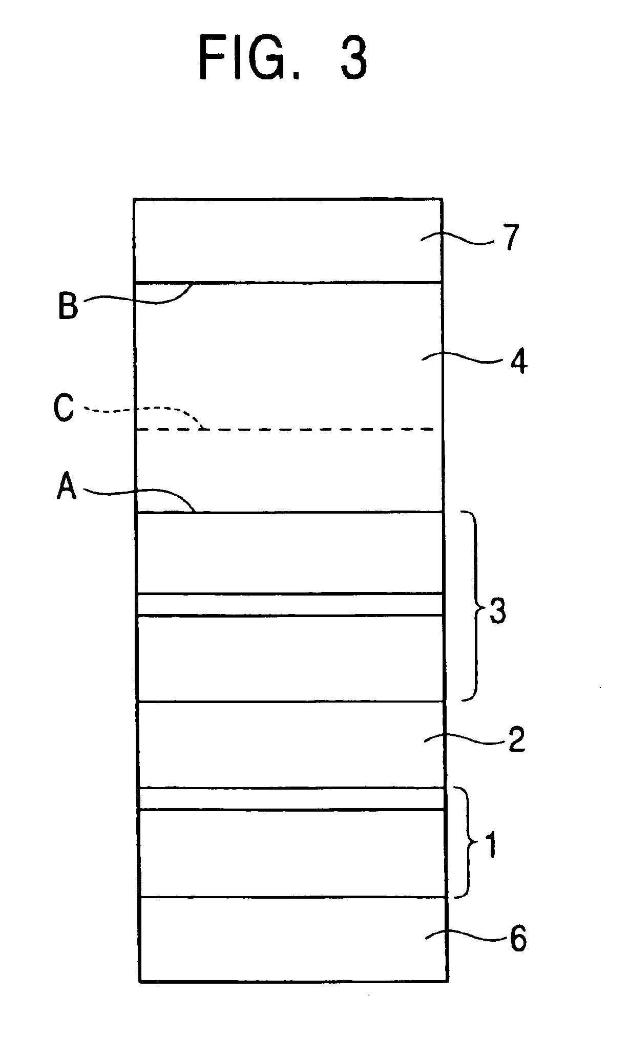
In accordance with the present invention, the antiferromagnetic layer is formed, for example, as follows. An ordered crystalline structure is readily formed and the antiferromagnetic properties are maximized when the ratio of Pt and Mn is set to 50:50. Such a composition ratio, however, serves to suppress the creation of a non-aligned crystal lattice state at the interface between ferromagnetic layer and the antiferromagnetic layer, resulting in an insufficient transformation from a disordered lattice to an ordered lattice under heat treatment and, hence, insufficient strength of the exchange coupling magnetic field.
The antiferromagnetic layer and the ferromagnetic layer may have different lattice constants, or different crystalline orientations, at at least part of the interface therebetween. In this invention, the antiferromagnetic layer and the ferromagnetic layer have the same crystalline orientation when the seed layer is used. Preferably, a non-aligned crystal lattice state exists at at least part of the above-mentioned interface. The presence of such a non-aligned crystal lattice state promotes the transformation of the antiferromagnetic layer into an ordered lattice, thus making it possible to obtain a large exchange coupling magnetic field.

Problems solved by technology

As a result, the inventors found that the strength of the exchange coupling magnetic field is still unsatisfactory, despite the use of the composition ratio between Pt and Mn which is ideal for a bulk.
This is attributable to the fact that the transformation from a disordered lattice to an ordered lattice is still insufficient despite of the heat treatment.

Method used


Image

  • Exchange coupling film and electoresistive sensor using the same
  • Exchange coupling film and electoresistive sensor using the same
  • Exchange coupling film and electoresistive sensor using the same

Examples


first embodiment

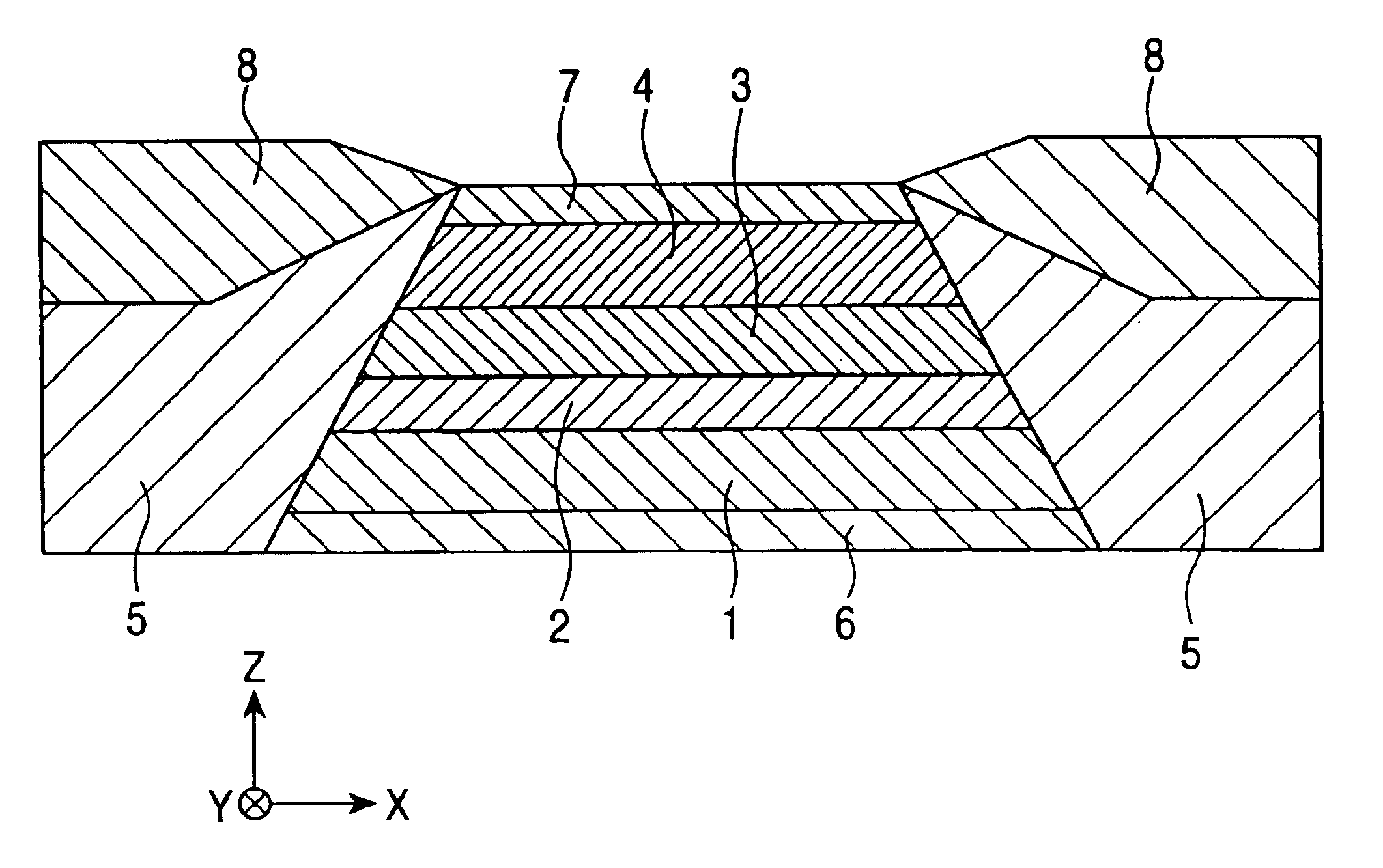
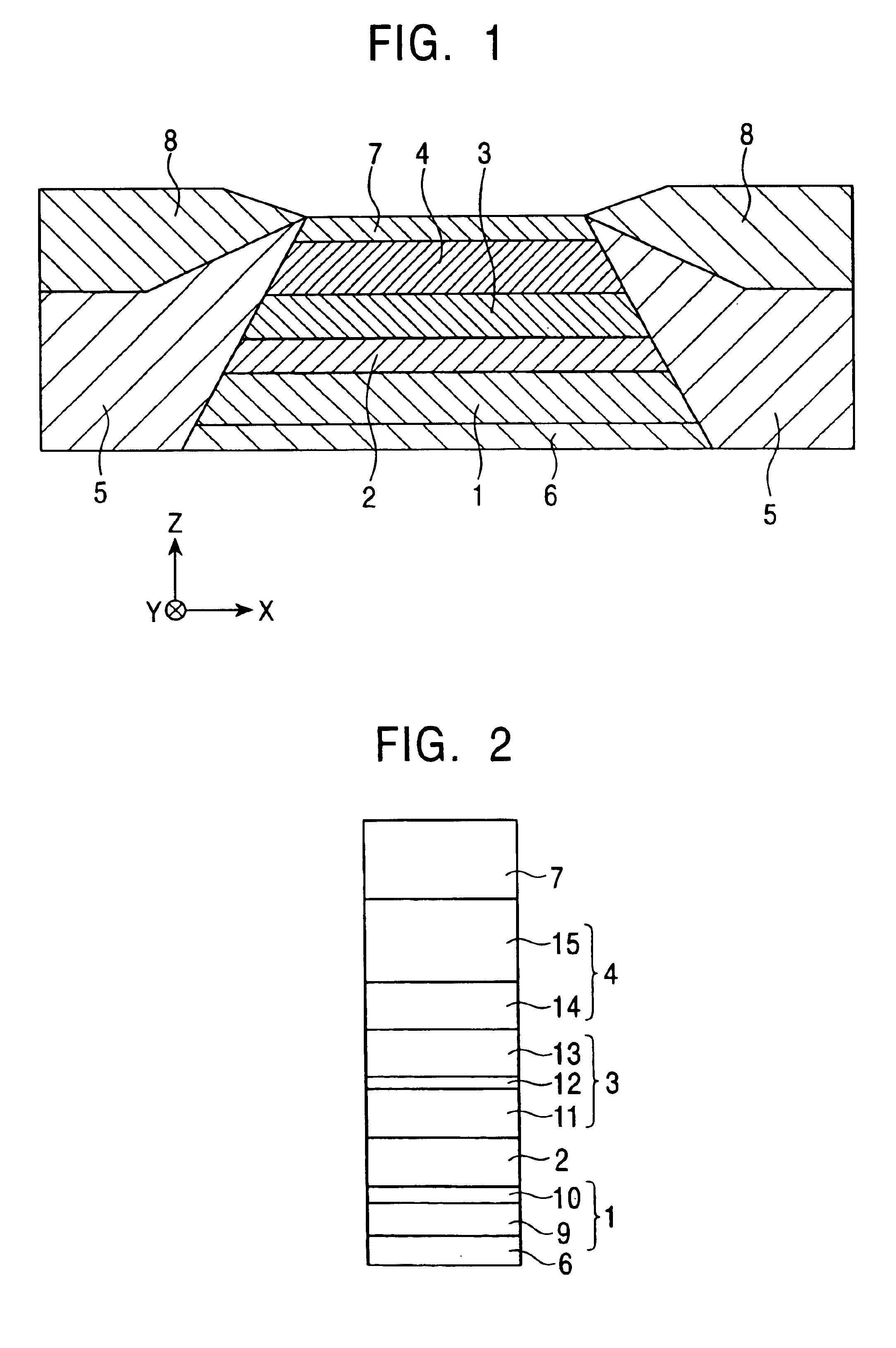
FIG. 1 is a cross-sectional view of a single spin valve type magnetoresistive sensor in accordance with the present invention, as viewed from the same side as the ABS surface. In this Figure, only the central portion of the device which extends in the X direction is shown in cross-sectional view.

This single spin valve type magnetoresistive sensor is provided on, for example, a trailing side end of a floating slider of a hard disk device, and is intended to detect, for example, the recording magnetic fields on the hard disk. A recording medium such as the hard disk moves in a Z direction, while the direction of the magnetic field leaking from the hard disk is indicated by Y.

Shown at the bottom of FIG. 1 is an underlying layer 6 which is formed of a non-magnetic material including selected from the group consisting of Ta, Hf, Nb, Zr, Ti, Mo, and W and combinations thereof. On the underlying layer 6 are deposited a free magnetic layer 1, a non-magnetic intermediate layer 2, a pinned ma...

example 1

The laminate structure was composed of the following layers, sequentially formed from the bottom layer: Underlying layer 6: Ta (50) / free magnetic layer 1:[Ni80Fe20(45) / Co(5)] / non-magnetic intermediate layer 2: Cu(25) / pinned magnetic layer 3: [Co(20) / Ru(8) / Co(15)] / first antiferromagnetic layer 14: Pt58Mn42 (10) / second antiferromagnetic layer: Pt50Mn50(110) / protective layer 7: Ta(30)

example 2

The laminate structure was composed of the following layers, sequentially formed from the bottom layer: Underlying layer 6: Ta (50) / free magnetic layer 1:[Ni80Fe20(45) / Co(5)] / non-magnetic intermediate layer 2: Cu(25) / pinned magnetic layer 3: [Co(20) / Ru(8) / Co(15)] / first antiferromagnetic layer 14: Pt58Mn42 (10) / second antiferromagnetic layer: Pt50Mn50(X-10) / protective layer 7: Ta(30)


PUM

PropertyMeasurementUnit
volume ratioaaaaaaaaaa
temperatureaaaaaaaaaa
temperaturesaaaaaaaaaa

Abstract

An exchange coupling film has an antiferromagnetic layer made of an antiferromagnetic material containing an element X and Mn, where the element X is selected from the group of elements consisting of Pt, Pd, Ir, Rh, Ru, and Os, and combinations thereof. The antiferromagnetic layer has a region in which the ratio of the atomic percent of the element X to Mn increases in a direction towards said ferromagnetic layer. The crystalline structure of at least part of said antiferromagnetic layer has a CuAu0I type face-centered square ordered lattice.

Description

BACKGROUND OF THE INVENTION1. Field of the InventionThe present invention relates to an exchange coupling film which has an antiferromagnetic layer and a ferromagnetic layer, wherein the direction of magnetization of the ferromagnetic layer is fixed in a predetermined direction by the effect of an exchange magnetic field which is generated at the interface between the antiferromagnetic layer and the ferromagnetic layer. More particularly, the present invention relates to an exchange coupling film which is improved to exhibit a large ratio of resistance variation and also to a magnetoresistive sensor, e.g., a spin valve thin-film device or an ARM device, incorporating such an exchange coupling film, as well as to a thin-film magnetic head which uses such a magnetoresistive sensor.2. Description of the Related ArtA spin-valve-type thin-film device is a kind of GMR (Giant Magnetoresistive) device which makes use of a giant magnetoresistive effect, and is used for detecting recording ma...

Claims


Application Information

Patent Timeline
Patent Type & Authority Patents(United States)
IPC IPC(8): G11B5/66G01R33/09G11B5/31G11B5/39H01F10/12H01F10/30H01F10/32H01L43/10
CPCB82Y25/00G01R33/093G11B5/31G11B5/3903G11B5/66H01F10/12H01F10/3268H01L43/10Y10T428/1143H01F10/3218Y10S428/90H01F10/123Y10T428/1121H01F10/30H10N50/85
Inventor SAITO, MASAMICHIHASEGAWA, NAOYAIDE, YOSUKETANAKA, KENICHI
Owner ALPS ALPINE CO LTD
Learn More