Embedded memory with security row lock protection

Active Publication Date: 2005-04-12
ATMEL CORP
View PDF5 Cites 20 Cited by
  • Summary
  • Abstract
  • Description
  • Claims
  • Application Information

AI Technical Summary

Benefits of technology

In one exemplary embodiment, the elements in the security row can be programmed to an unlocked state in which the elements do not conduct current when the security row is selected, and therefore have no effect on the bit lines or security bit lines, and consequently, no effect on the ability to read the contents of the internal embedded memory elements. Alternatively, the security row elements can be programmed to a locked state in which the security row elements conduct current anytime that the security row is selected. For the security row elements connected to bit lines, selecting the security row causes all I/O sense-amplifier (“sense-amp”) outputs to always detect and output a logic zero (“0”) value, regardless of the true memory contents of a concurrently selected memory array row. For the security row elements connected to the security bit lines, selecting a security row causes a lockbit sense amplifier (“lockbit sense-amp”) to always detect and output a logic zero (“0”) value, which corresponds to a lockbit LOCK condition. Logic circuits cause the security row to be selected for external memory read requests. Selection of the security row in parallel with the requested memory row ensures tha

Problems solved by technology

Incorporating security rows with bit line elements, security bit line elements, or a combination of the two, increases the ove

Method used


Image

  • Embedded memory with security row lock protection
  • Embedded memory with security row lock protection

Examples


Embodiment Construction

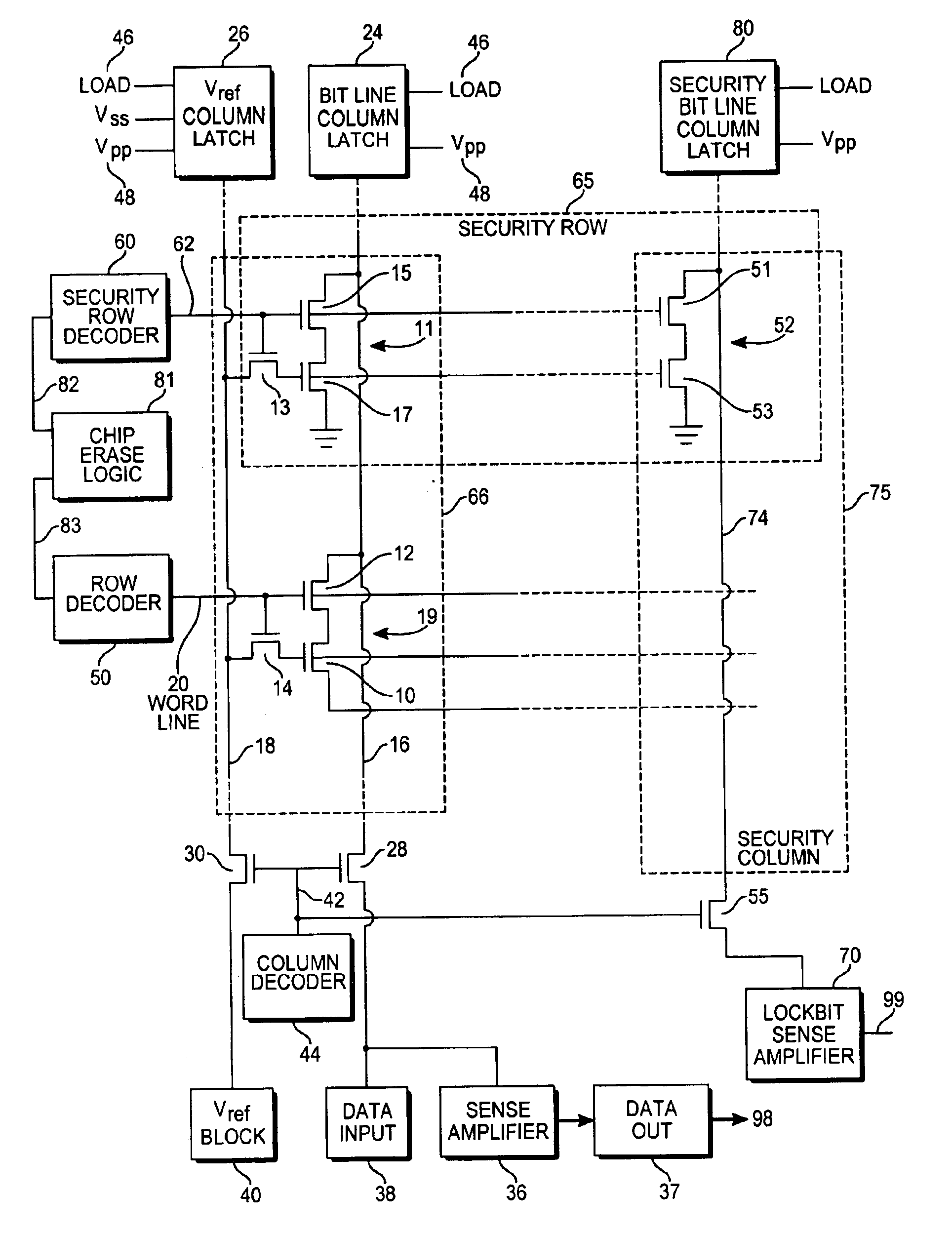
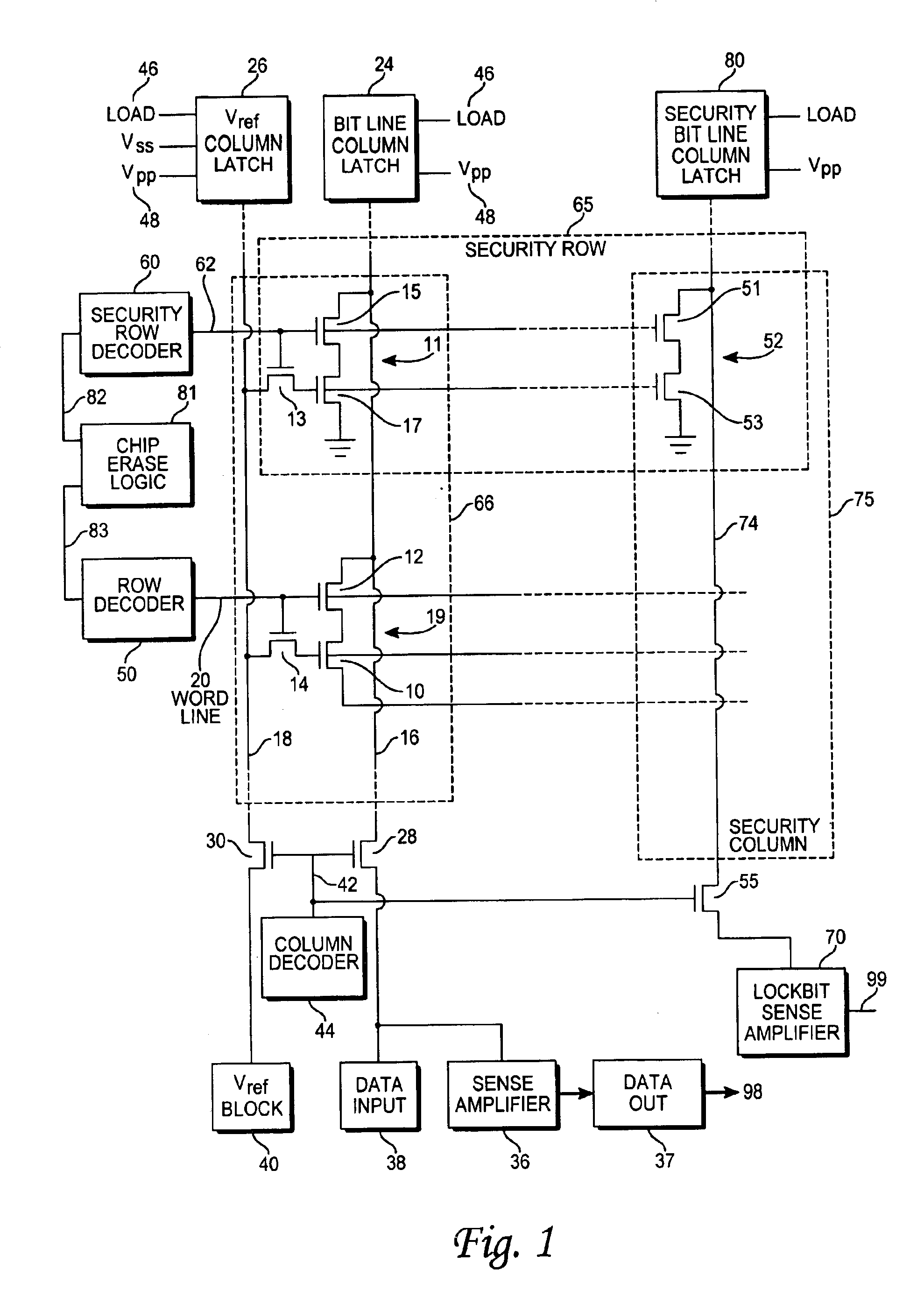
With reference to FIG. 1, a semiconductor memory incorporating an exemplary embodiment of the present invention is shown. The semiconductor memory element shown in FIG. 1 is an electrically erasable and programmable non-volatile memory cell (EEPROM), but the invention can be implemented by one of ordinary skill into other types of non-volatile memory cells, such as, for example, a flash memory cell. In the EEPROM array of FIG. 1, each floating gate transistor 10 is paired up with an access transistor 12, forming a memory cell 19, in which the source of the access transistor 12 is connected to the drain of the floating gate transistor 10. Each of the memory cells are arranged into a memory array structure, with the various bit lines 16 and word lines 20 arranged in an array as shown in FIG. 1. The drain of the access transistor 12 taps into a bit line 16 that is common to the drains of all of the access transistors 12 in the same column 66. A bit line column latch 24 is connected to ...


PUM


Abstract

A memory device having a memory array of nonvolatile memory elements also includes one or more security rows (or columns) of security bits that can be programmed to a locked status. External memory access requests are processed by first reading the corresponding security bit. If the requested row or column is locked, a default zero value is returned. Only external requests of unlocked locations, and all internal access requests, return the actual memory contents. Security bits can be erased (unlocked), but the secured contents of the locked row or column is also erased at the same time.

Description

TECHNICAL FIELDThe present invention relates to semiconductor memory devices and more specifically to a semiconductor memory having a security feature to prevent unauthorized access to the contents of the memory.BACKGROUND ARTSemiconductor memory devices, such as non-volatile memories and the like, usually include embedded memories, such as the code memory in flash microcontrollers, which may contain proprietary programs that should not be accessible to anyone, especially one's competitors. These embedded memories require security features that allow users to program the contents of the memory, verify the contents of the memory, and then disable the memory from ever being read externally again.Some prior art methods of protecting the contents of embedded memories include the use of lockbit features that prevent the embedded memory (hereinafter “memory”) from being read outside of a device in which it is embedded after locking. The lockbit is a type of programmable, non-volatile memo...

Claims


Application Information

Patent Timeline
IPC IPC(8): G11C7/00G11C16/04G11C7/10G11C7/24G11C8/20
CPCG11C7/1006G11C8/20G11C7/24G11C2207/104
Inventor CURRY, DUNCAN
Owner ATMEL CORP
Why Eureka
Try Eureka