Signatures for facilitating hot upgrades of modular software components

a software component and hot upgrade technology, applied in the direction of generating/distributing signals, instruments, data switching networks, etc., can solve the problems of data loss, network outage, service providers incur downtime due to failures, etc., and achieve the effect of accurately determining the upgrade status of each software component and facilitating hot upgrades of software components

Inactive Publication Date: 2005-04-12
CIENA
View PDF37 Cites 431 Cited by
  • Summary
  • Abstract
  • Description
  • Claims
  • Application Information

AI Technical Summary

Benefits of technology

[0035]The present invention provides a method and apparatus for facilitating hot upgrades of software components within a telecommunications network device through the use of “signatures” generated by a signature generating program. After installation of a new software release within the network device, only those software components whose signatures do not match the signatures of corresponding and currently executing software components are upgraded. Signatures promote hot upgrades by identifying only those software components that need to be upgraded. Since signatures are automatically generated for each software component as part of putting together a new release a quick comparison of two signatures provides an accurate assurance that either the software component has changed or has not. Thus, signatures provide a quick, easy way to accurately determine the upgrade status of each software component.

Problems solved by technology

The majority of Internet outages are directly attributable to software upgrade issues and software quality in general.
Mitigation of network downtime is a constant battle for service providers.
Service providers not only incur downtime due to failures, but also for upgrades (i.e., deployment of new or improved software and / or hardware) or software and / or hardware patches that are needed to correct current network problems.
A network outage can also occur after an upgrade has been installed if the upgrade itself includes undetected problems (i.e., bugs) or if the upgrade causes other software or hardware to have problems.
Upgrades often result in data loss due to incompatibilities with data file formats.
Downtime may occur unexpectedly days after an upgrade due to lurking software or hardware incompatibilities.
Often, the upgrade of one process results in the failure of another process.
Unfortunately, the data and code within the image is static and cannot be changed without changing the entire image.
Shutting down a network router or switch immediately affects the network up time or availability.
To minimize the number of reboots required for software upgrades and, consequently, the amount of network down time, new software releases to customers are often limited to a few times a year at best.
In addition, new software releases are also limited to a few times a year due to the amount of testing required to release a new monolithic software program.
As the size and complexity of the program grows, the amount of time required to test and the size of the regress matrix used to test the software also grows.
Forcing more releases each year may negatively affect software quality as all bugs may not be detected.
If the software is not fully tested and a bug is not detected or even after extensive testing a bug is not discovered and the network device is rebooted with the new software, more network down time may be experienced if the device crashes due to the bug or the device causes other devices on the network to have problems and it and other devices must be brought down again for repair or another upgrade to fix the bug.
In addition, after each software release, the size of the monolithic image increases leading to a longer reboot time.
Moreover, a monolithic image requires contiguous memory space, and thus, the computer system□s finite memory resources will limit the size of the image.
Unfortunately, limiting the number of software releases also delays the release of new hardware.

Method used


Image

  • Signatures for facilitating hot upgrades of modular software components
  • Signatures for facilitating hot upgrades of modular software components
  • Signatures for facilitating hot upgrades of modular software components

Examples


Embodiment Construction

having multiple sub-processes;

[0075]FIG. 28 is a block diagram of a hierarchical fault descriptor;

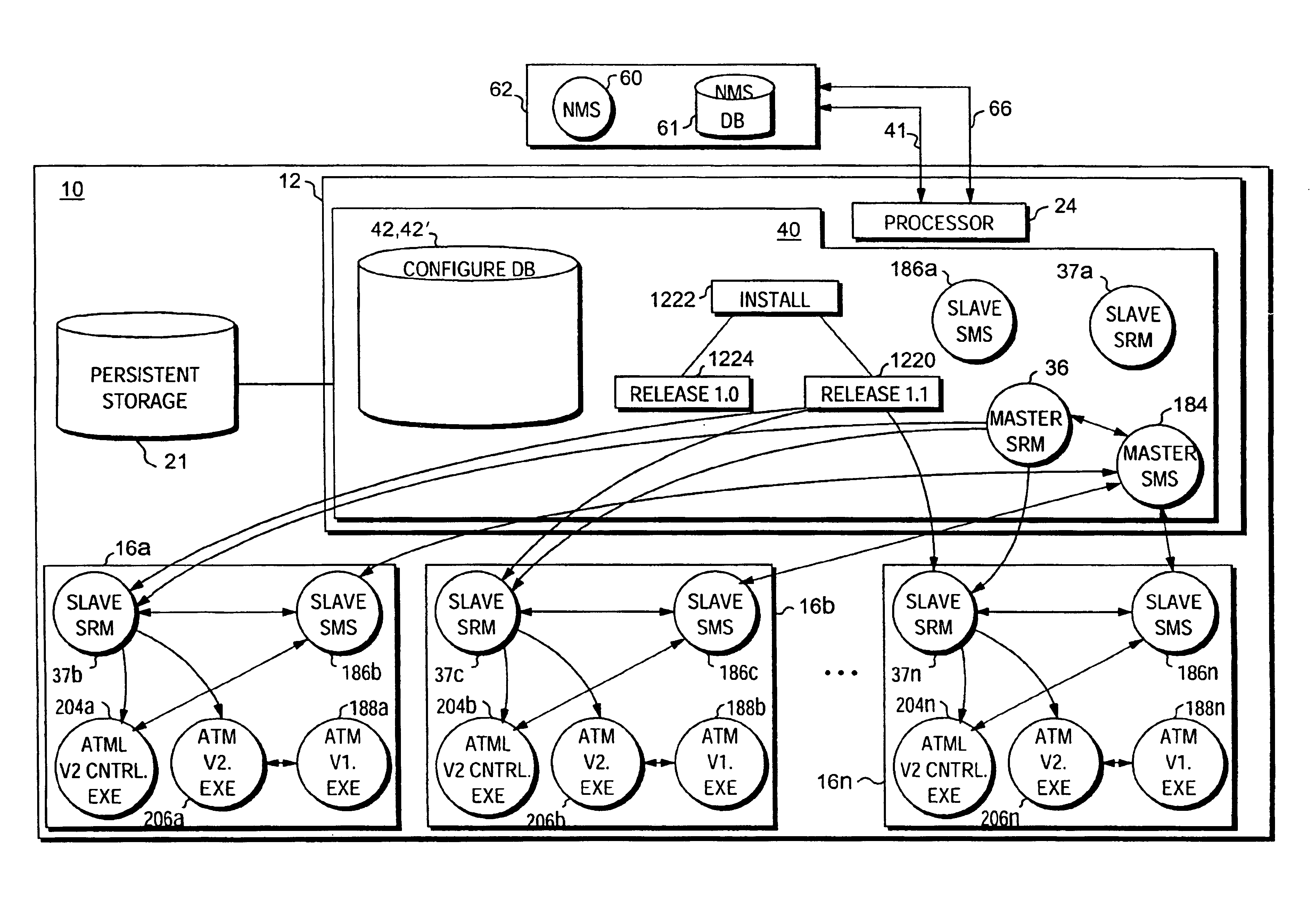
[0076]FIG. 29 is a block and flow diagram of a computer system incorporating a distributed redundancy architecture and illustrating a method for accomplishing distributed software redundancy;

[0077]FIG. 30 is a table representing data in a configuration database;

[0078]FIGS. 31a-31c, 32a-32c, 33a-33d and 34a-34b are block and flow diagrams of a computer system incorporating a distributed redundancy architecture and illustrating methods for accomplishing distributed redundancy and recovery after a failure;

[0079]FIG. 35 is a block diagram of a network device;

[0080]FIG. 36 is a block diagram of a portion of a data plane of a network device;

[0081]FIG. 37 is a block and flow diagram of a network device incorporating a policy provisioning manager;

[0082]FIGS. 38 and 39 are tables representing data in a configuration database;

[0083]FIG. 40 is an isometric view of a network device;

[0084]FIGS. 41a-...


PUM


Abstract

The present invention provides a method and apparatus for facilitating hot upgrades of software components within a telecommunications network device through the use of “signatures” generated by a signature generating program. After installation of a new software release within the network device, only those software components whose signatures do not match the signatures of corresponding and currently executing software components are upgraded. Signatures promote hot upgrades by identifying only those software components that need to be upgraded. Since signatures are automatically generated for each software component as part of putting together a new release a quick comparison of two signatures provides an accurate assurance that either the software component has changed or has not. Thus, signatures provide a quick, easy way to accurately determine the upgrade status of each software component.

Description

RELATED APPLICATIONS[0002]This application is a continuation-in-part of application number[0003]Ser. No. 09 / 756,936 files Jan. 9, 2001 which is a C-I-P of[0004]Ser. No. 09 / 718,224 filed Nov. 21, 2001 which is a C-I-P of[0005]Ser. No. 09 / 711,054 filed Nov. 9, 2000 which is a C-I-P of[0006]Ser. No. 09 / 703,856 filed Nov. 1, 2000 which is a C-I-P of[0007]Ser. No. 09 / 687,191 filed Oct. 12, 2000 now abandoned which is a C-I-P of[0008]Ser. No. 09 / 669,364 filed Sep. 26, 2000 which is a C-I-P of[0009]Ser. No. 09 / 663,947 filed Sep. 18, 2000 now abandoned which is a C-I-P of[0010]Ser. No. 09 / 656,123 filed Sep. 6, 2000 now abandoned which is a C-I-P of[0011]Ser. No. 09 / 653,700 filed Aug. 31, 2000 now abandoned which is a C-I-P of[0012]Ser. No. 09 / 637,800 filed Aug. 11, 2000 which is a C-I-P of[0013]Ser. No. 09 / 633,675 filed Aug. 7, 2000 which is a C-I-P of[0014]Ser. No. 09 / 625,101 filed Jul. 24, 2000 which is a C-I-P of[0015]Ser. No. 09 / 616,477 filed Jul. 14, 2000 which is a C-l-P of[0016]Ser. ...

Claims


Application Information

Patent Timeline
Patent Type & Authority Patents(United States)
IPC IPC(8): G06F1/14H04L29/06H04L7/00H04J3/06H04L12/24H04L12/56
CPCG06F1/14H04L69/18H04L7/0008H04L29/06H04L41/22H04L45/50H04L63/102H04L63/105H04L63/12H04J3/0685H04L41/082H04L41/0843H04L41/0856H04L41/0866H04L41/0889H04L9/40
Inventor KIDDER, JOSEPH D.MAHLER, MICHAEL B.PERREAULT, EDWARD L.STEARNS, MARGARETHURLEY, JIM
Owner CIENA
Why Eureka
Try Eureka