
Method and apparatus for radio packet data transmission

a radio packet data and apparatus technology, applied in the field of radio packet data transmission apparatus, can solve the problems of data crash, data cannot be processed in time, and the plurality of subscribers cannot be accepted, so as to reduce the pre-processing time of packet data transmission

Inactive Publication Date: 2005-04-12
LG ELECTRONICS INC
View PDF6 Cites 103 Cited by
  • Summary
  • Abstract
  • Description
  • Claims
  • Application Information

AI Technical Summary

Benefits of technology

Another object of the present invention is to provide an apparatus and a method for radio packet data transmission by which the pre-processing time of packet data transmission can be reduced.
Another object of the present invention is to deal with an error that may be generated while transmitting the data quickly.

Problems solved by technology

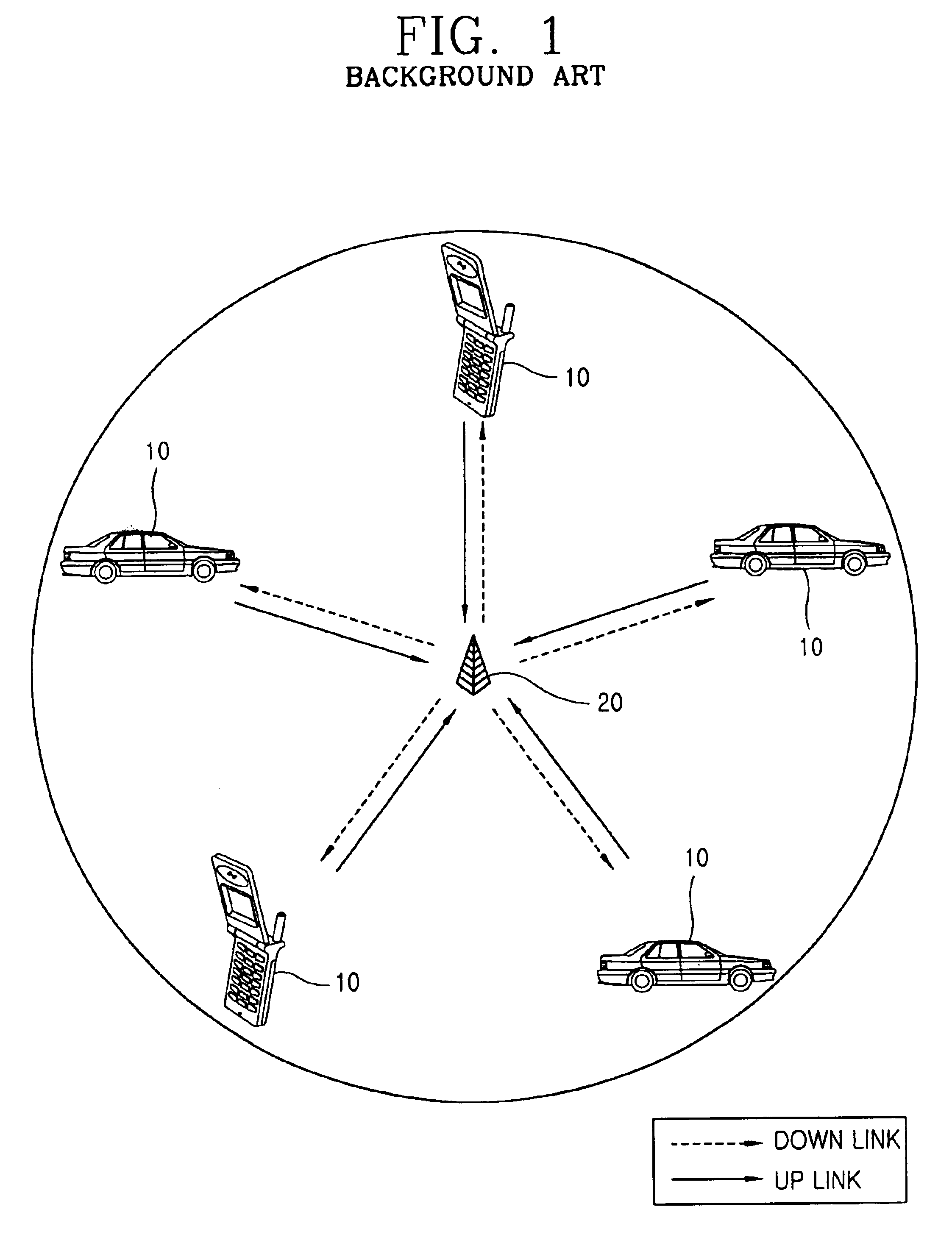
That is, a plurality of subscribers are not able to be accepted at the same time, because of the limited frequency source.
Also, after the pre-processing data is transmitted, an error in the transmitted data can only be identified after the data transmission is finished.
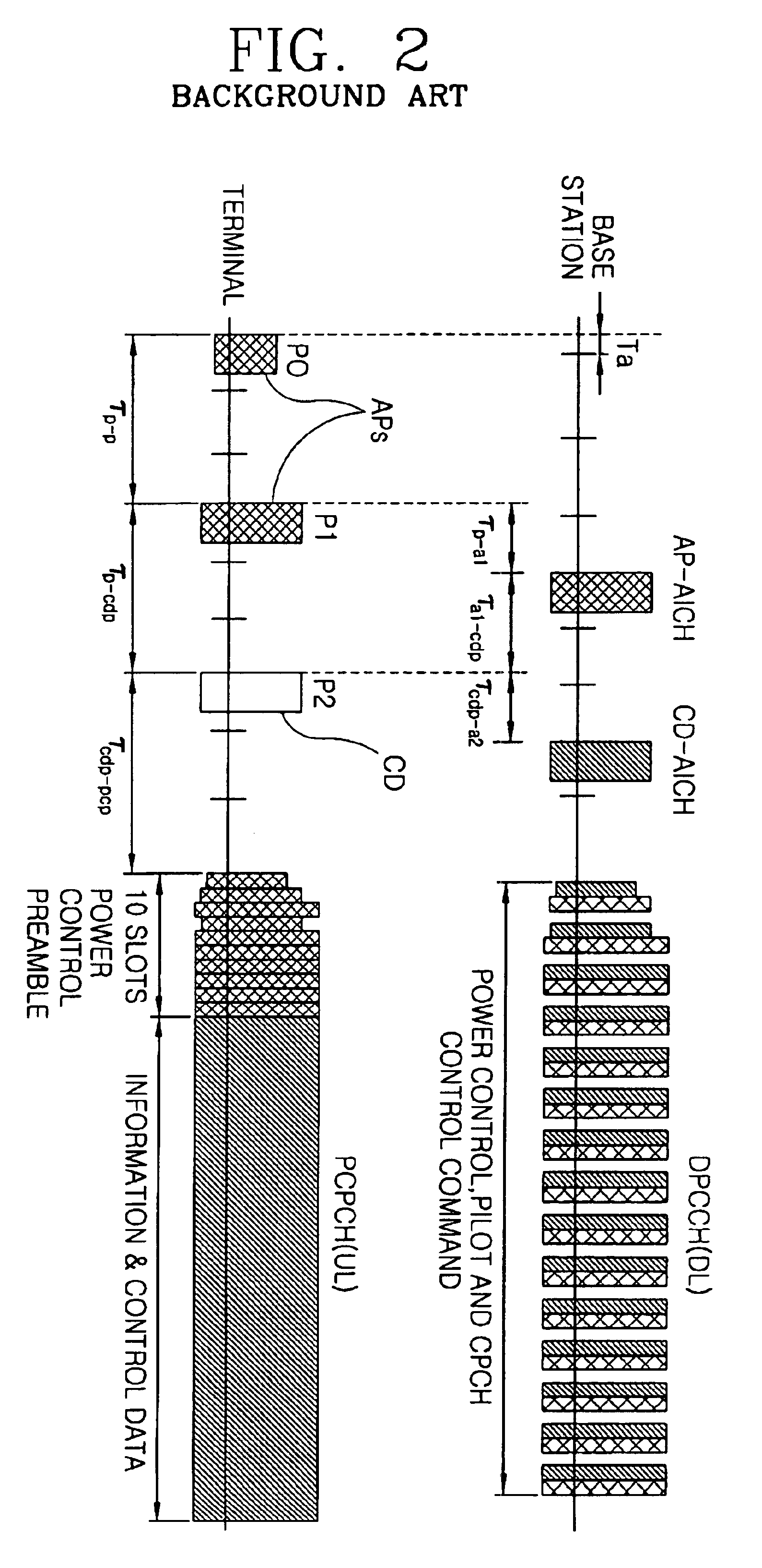
Also, a Common Packet Channel (CPCH) method of 3GPP, which is decided by the ESTI, ARIB / TTC, TI, and TTA in order to set detailed standards for the background art third generation GMS network, the W-CDMA connecting technique, and for the terminal, has problems that data crashes are increased if there are many subscribers who are assigned a certain channel.
Additionally, the data transmission process is complex and it is difficult to transmit the data at high speed because overhead data, which control the respective packets, are large.

Method used


Image

  • Method and apparatus for radio packet data transmission
  • Method and apparatus for radio packet data transmission
  • Method and apparatus for radio packet data transmission

Examples


Embodiment Construction

FIG. 3 is a block diagram showing a terminal 10 apparatus according to the present invention. The terminal 10 has an Intermediate Frequency / Radio Frequency (IF / RF) unit 100 that changes a radio frequency signal transmitted from the base station 20 into a baseband signal and transmits the baseband signal to a receive unit 120. Additionally, the IF / RF unit 100 changes a baseband signal from the sending unit 130 into a radio frequency signal. A receive unit 120 extracts a data signal from the transmitted baseband signal and applies the extracted signal to a data matching unit 150. A data matching unit 150 matches signals inputted / outputted between the terminal 10 and an outer data processing device, to change the signal outputted from the receive unit 120 to be used in the outer data processing device and change the signal outputted from the outer data processing device to be used in the terminal 10. A controlling channel supervising unit 110 controls the transmission electric power of...


PUM


Abstract

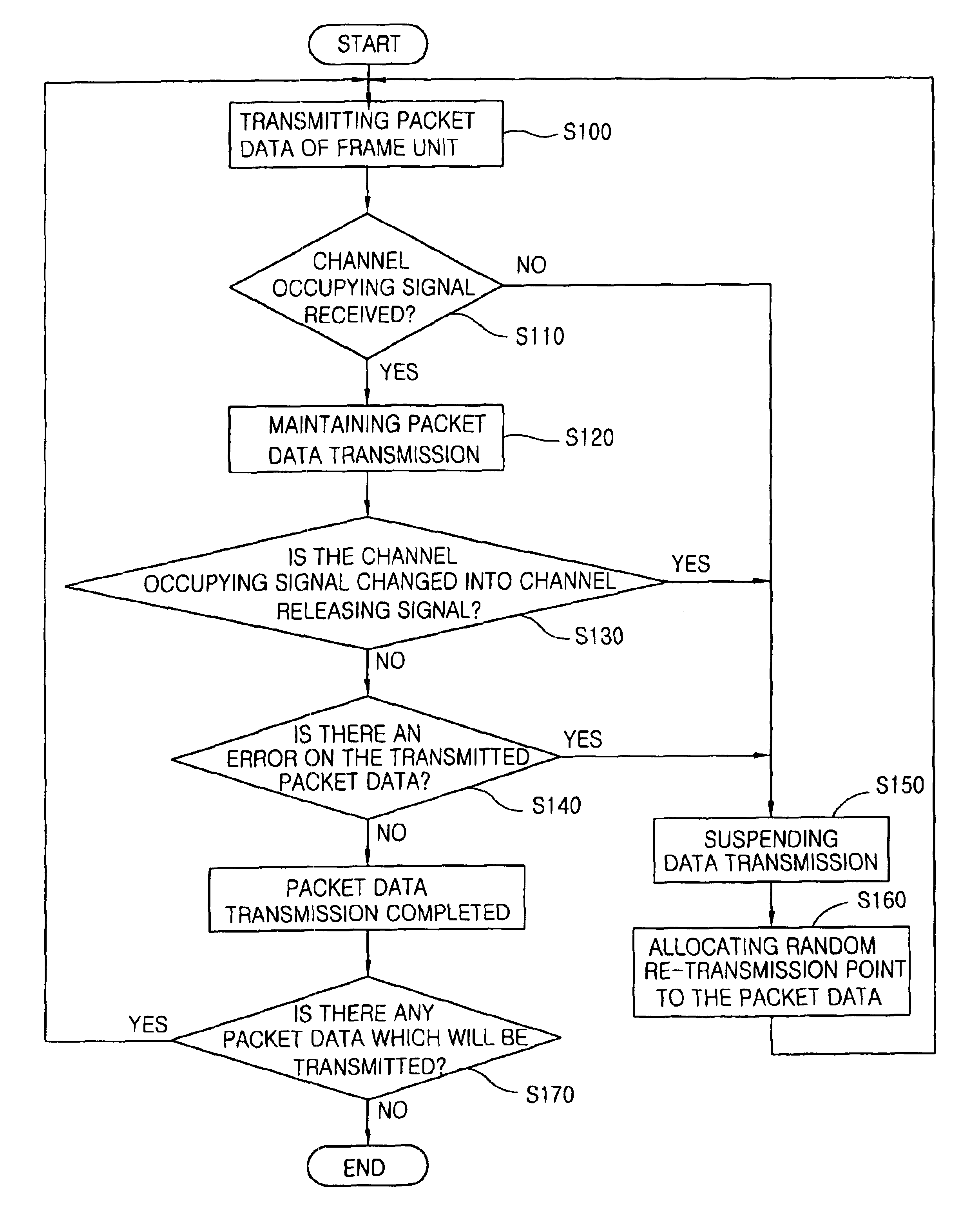
A method and device for communicating data within a packet frame unit between a terminal and a base station are disclosed. The terminal communicates the packet data to the base station. In response, the base station transmits a channel occupying signal, if the data transmission from the terminal is perceived by the base station. The terminal continues the communication of the packet data, while the channel occupying signal is active, determines whether the base station receives the communicated packet data, and ends the process for communicating the packet data if the base station receives the communicated packet data. If the base station fails to receive the communicated packet data, the terminal is informed through the channel occupying signal. Thereafter, the terminal discontinues its communication and then re-attempts to communicate the packet data from the beginning.

Description

BACKGROUND OF THE INVENTION1. Field of the InventionThe present invention relates to a transmission of radio packet data and, more particularly, to an apparatus and a method for radio packet data transmission.2. Background of the Related ArtA radio packet data transmission system is a system that transmits packet data by assigning a channel or time slot to respective subscriber terminals, which are connected to the system. In addition, a plurality of subscribers are able to communicate at high speed using a limited number of channels. A radio communication system using a frequency source should provide fast communication service to many subscribers using limited frequency channels.A radio communication system may use either a circuit method or a packet method for communicating information. The circuit method is a method of assigning a channel to a respective subscriber. Therefore, if there are many subscribers, a plurality of channels should be secured. That is, a plurality of subsc...

Claims


Application Information

Patent Timeline
Patent Type & Authority Patents(United States)
IPC IPC(8): H04L1/16H04L1/18H04L12/56
CPCH04L1/1887H04W52/48H04W74/04
Inventor KIM, YOUNG HWANMOON, DOO YOUNGLEE, KYUNG KUK
Owner LG ELECTRONICS INC
Learn More