
Method of controlling direct gasoline injection type internal combustion engine with turbocharger and direct gasoline injection type internal combustion engine with turbocharger

a technology of direct gasoline injection and internal combustion engine, which is applied in the direction of electric control, ignition automatic control, machines/engines, etc., can solve the problems of incomplete combustion, smoke generation, and excessive air-fuel mixture around the ignition plug, and achieve the effect of reducing the exhaust gas

Inactive Publication Date: 2005-04-19
HITACHI LTD
View PDF5 Cites 29 Cited by
  • Summary
  • Abstract
  • Description
  • Claims
  • Application Information

AI Technical Summary

Benefits of technology

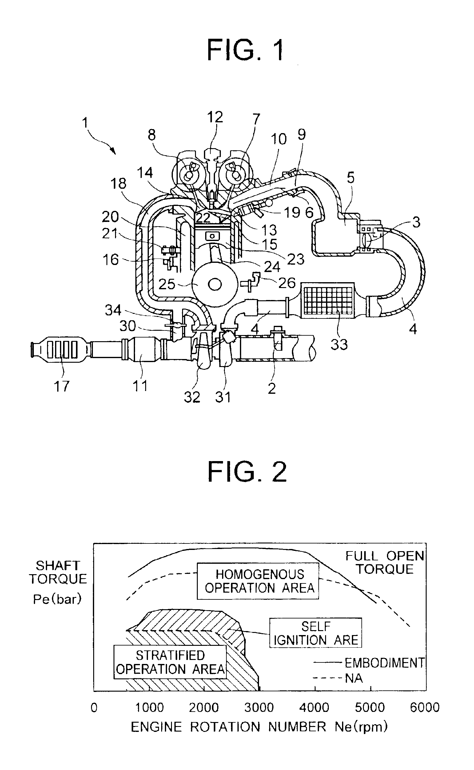
[0010]The present invention is made by taking the matters mentioned above into consideration, and a first object of the present invention is to reduce an exhaust gas in a lean burn area which is expanded by a supercharging, in a direct gasoline injection engine provided with a turbocharger. A second object of the present invention is to prevent a knocking and a misfire at a time of self ignition combustion.

Problems solved by technology

It is possible to expand the lean burn area by making the air fuel ratio small, however, since a fuel injection amount is also increased, an air-fuel mixture around an ignition plug becomes too rich.
Accordingly, there is a problem that an incomplete combustion is generated and a smoke is generated.
In accordance with the technique described in the prior art mentioned above, the lean burn area can be expanded while inhibiting the smoke discharge, however, there is listed up a new problem that an NOx discharge amount is increased in proportion to the increased air amount.
Since the rich spike control additionally injects the fuel which does not contribute to the combustion, the specific fuel consumption is deteriorated.
Accordingly, it is possible to improve the specific fuel consumption by expanding the lean burn area in accordance with the supercharging, however, there is generated a problem that the specific fuel consumption is deteriorated by the increase of the number of rich spike control and the fuel injection amount which are caused by the increase of NOx discharge amount.
However, since this engine does not have any ignition source, it is hard to control the ignition and the combustion in a wide operation area of the engine, and the technique has not been established yet.
Further, since the operation area on the basis of the compression ignition is limited to a very narrow range having a low speed and a low load, a lot of efforts for expanding the area have been executed.
However, none of the techniques are sufficient for the engine employed in a motor vehicle.
Accordingly, it is possible to expand the operable range on the basis of the lean burn which is advantageous in view of improving the specific fuel consumption in the direct gasoline injection engine, however, since the rich spike control is required in view of the structure of the exhaust system provided with the NOx catalyst, there is a problem that the specific fuel consumption is not improved in an actual traveling condition.
Further, in the compression ignition engine which can construct the exhaust system requiring no NOx catalyst, there has not been established a technique which can achieve the low NOx combustion in a wide operation range.
Accordingly, none of the techniques are sufficient in view of the engine system which can achieve both of the improvement of specific fuel consumption and the reduction of exhaust gas.

Method used


Image

  • Method of controlling direct gasoline injection type internal combustion engine with turbocharger and direct gasoline injection type internal combustion engine with turbocharger
  • Method of controlling direct gasoline injection type internal combustion engine with turbocharger and direct gasoline injection type internal combustion engine with turbocharger
  • Method of controlling direct gasoline injection type internal combustion engine with turbocharger and direct gasoline injection type internal combustion engine with turbocharger

Examples


Embodiment Construction

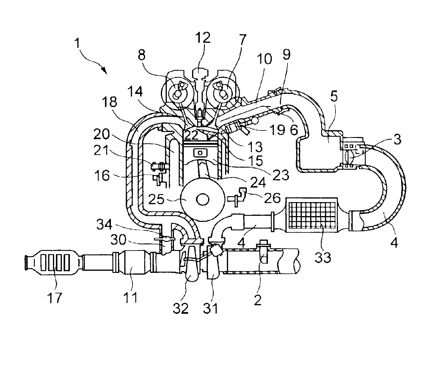
[0050]A description will be given of an embodiment which is obtained by embodying the present invention into a gasoline engine system for a motor vehicle, with reference to the accompanying drawings.

[0051]A gasoline engine system 1 shown in FIG. 1 is provided with an intake system which introduces an air to an engine, an exhaust system which discharges a combustion gas output from the engine, and a turbocharger which is placed within pipes of the intake system and the exhaust system.

[0052]The intake system is provided with an air amount sensor 2 which measures an amount of air introduced from an air cleaner (not shown), a compressor 31 which supercharges the introduced air, an intake passage 4 which connects the compressor 31 to a throttle valve 3, an intake manifold 9 which distributes the air passing through the throttle valve 3 into respective cylinders, and a surge tank 5 which is provided between the intake manifold 9 and the throttle valve 3 for inhibiting an intake air pulsat...


PUM


Abstract

A first object of the invention is to reduce an exhaust gas in a lean burn area which is expanded by a supercharging, in a direct gasoline injection type internal combustion engine provided with a turbocharger. A second object of the invention is to prevent a knocking and a misfire at a time of self ignition combustion. The invention is used for the direct gasoline injection type internal combustion engine provided with the turbocharger. In order to achieve the first object, a combustion mode is switched from a stratified combustion mode to a self ignition combustion mode at a time when a suction pressure of the engine is equal to or more than an atmospheric pressure. Further, in order to achieve the second object, an ignition timing is set to a range between a top dead center and 10 degrees after the top dead center (0 to 10 (ATDC)) at a time of operating an engine in accordance with a self ignition combustion mode.

Description

BACKGROUND OF THE INVENTION[0001]1. Field of the Invention[0002]The present invention relates to a method of controlling a direct gasoline injection type internal combustion engine with a turbocharger, and more particularly to a control method for improving a combustion at a time of being operated under a high load, purifying an exhaust gas and improving a specific fuel consumption.[0003]2. Description of the Related Art[0004]In a lean burn engine as typified by a direct gasoline injection engine, for the purpose of improving a specific fuel consumption, in an operation area having a low engine torque, an internal combustion engine is operated under a state in which an air is excess in comparison with a theoretical air fuel ratio, that is, under a so-called lean burn state. In the case that the lean burn is executed, an air amount which is defined by a fuel amount for achieving a torque required by a driver and a predetermined air fuel ratio is limited by an air volume displacement ...

Claims


Application Information

Patent Timeline
IPC IPC(8): F01N3/08F02D37/00F02D41/00F02D37/02F02B1/12F02D13/02F02B37/18F02B1/00F02D41/30F01N3/20F01N7/00F01N7/02F02B23/10F02B75/12F02B37/00F02B75/00F01N13/02F02B11/00F02B17/00F02D23/00F02D41/02F02D43/00F02D45/00F02P5/15
CPCF01N3/0814F01N13/009F02B1/12F02B37/18F02D13/0219F02D13/0265F02D41/3047F02D41/307F01N3/0842F01N3/20F01N2570/10F01N2570/12F01N2570/14F02B23/105F02B37/00F02B2075/125F02D41/3029F02D2200/0406Y02T10/18Y02T10/123Y02T10/144Y02T10/12
Inventor SHIRAISHI, TAKUYAYAMAOKA, SHIROUTOKUYASU, NOBORUOHSUGA, MINORU
Owner HITACHI LTD
Learn More