Muffler for suction system exhaust air used with an automatic cutting machine

a technology of automatic cutting machine and suction system, which is applied in the field of mufflers, can solve the problems of intense noise in the surrounding area and hazardous to employees who must work in the area, and achieve the effect of enhancing noise reduction and reducing noise level to human beings

Inactive Publication Date: 2005-04-19
DONDI BEDA CHARLES
View PDF33 Cites 18 Cited by
  • Summary
  • Abstract
  • Description
  • Claims
  • Application Information

AI Technical Summary

Benefits of technology

[0008]The present invention comprises a device for reducing noise generated by an air turbine especially used as a suction device for an automatic cutting table comprising a first main housing which is essentially a hollow elongated conduit, an exhaust housing, and an internal baffle arrangement and noise reduction material to significantly reduce air exhaust noise. An air inlet to the main housing is connected to the turbine exhaust from the turbine. Noise reduction material is strategically mounted within the main housing and exhaust housing which interacts with the baffle elements.
[0012]In an alternate embodiment, for much larger turbines and electric motors having 25 horsepower or more, the present invention can be mounted vertically to include a cylindrically shaped rigid exhaust housing containing a first large rectangular baffle having numerous small apertures for diverting exhausting air connected directly to the exhaust duct of the large turbine. The exhaust housing enclosing the baffle is mounted vertically and includes an extremely large interior chamber that receives outlet air from the upstream rectangular baffle. The exhaust housing can be a cylindrically-shaped container having an open, lower end that is coaxially mounted with the rectangular inlet baffle disposed along the longitudinal central axis of the exhaust housing. The inside cylindrical wall of the exhaust housing is lined with two inches of noise reduction foam. The exhaust duct from the turbine is rectangular and is connected directly to the baffle. In the alternate embodiment, the turbine exhaust air comes through the baffle, passing from the inside to the outside of the baffle though holes in the baffle, into the exhaust housing, changing direction 180 degrees and finally exiting out through openings in the lower end of exhaust housing back towards the turbine. The air is directed against the air turbine and electric motor for cooling purposes. Even though this is a large turbine and electric motor, the size and volume of the present invention fits well because it is mounted above the turbine and engine assembly for compactness without requiring additional space throughout the factory floor.
[0013]The use of the present invention has shown to greatly diminish decibels of noise experienced in the environment for medium and large size turbines used with cutting tables in a factory environment. The invention is very compact, is low in cost to manufacture and significantly improves the environment by reducing noise for workers.
[0015]It is another object of this invention to provide an improved muffler and sound reduction for air turbines used to create suction in a factory environment to greatly reduce the noise level to human beings.
[0016]And yet still another object of this invention is to provide a very compact noise reduction system for use in a factory environment for enhanced noise reduction of noise generated by an air turbine typically used to provide suction to an automatic fabric cutting table.

Problems solved by technology

As a result of the air exhaust from the turbine the surrounding area has intense noise from the high-energy air in the high decibel range.
This is very hazardous to employees who must work in the area.

Method used


Image

  • Muffler for suction system exhaust air used with an automatic cutting machine
  • Muffler for suction system exhaust air used with an automatic cutting machine
  • Muffler for suction system exhaust air used with an automatic cutting machine

Examples


Embodiment Construction

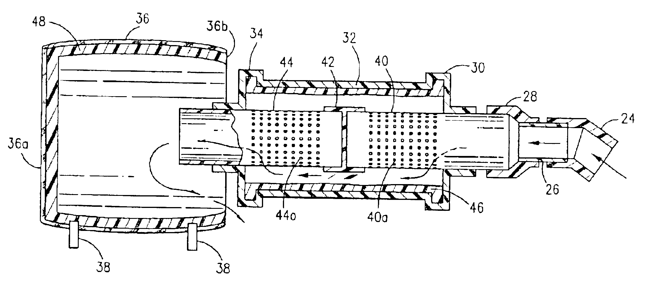
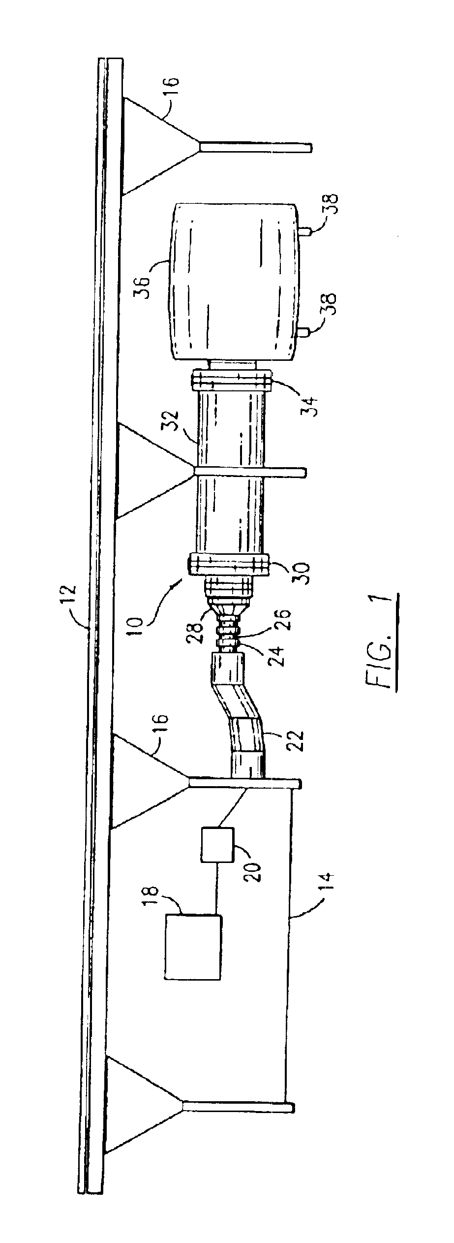
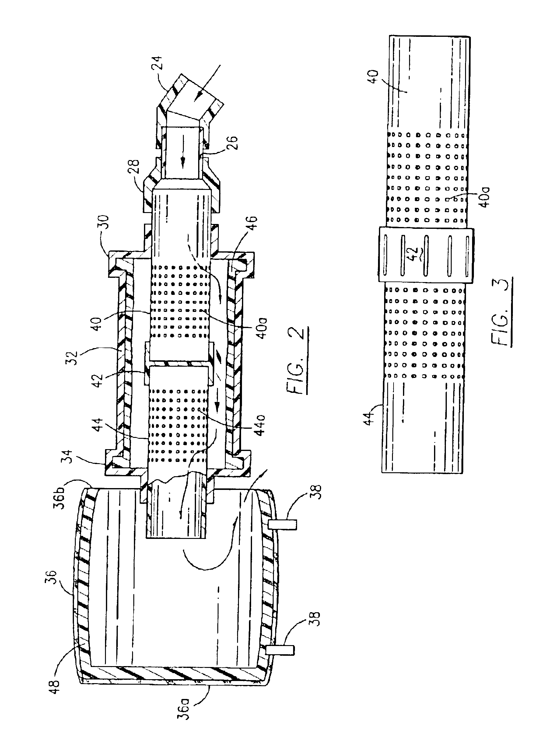
[0023]Refering now to the drawings and in particular to FIG. 1, the present invention is shown generally at 10 as a noise reduction system connected to a turbine 20 driven by electric motor 18 both of which are mounted under automatic cutting board table 12 behind a single baffle board 14. The turbine 20 has an exhaust conduit 22 and delivers high velocity air from the suction environment used to provide suction to table 12. The table is supported horizontally by vertical legs 16. The turbine 20 exhaust conduit 22 is in fluid communication and connects to the noise reduction system 10 though pipe couplings 24, 26 and 28. The inlet conduit 28 is connected to main housing end plate 30. The main housing 32 of the present invention is a large tubular, hollow conduit made of a rigid plastic material that is airtight and connected on the outlet side to end plate 34. An exhaust housing 36 is mounted at the outlet end of main housing 32 and supported by leg members 38 for mounting purposes....


PUM


Abstract

A noise reduction system for significantly reducing the noise generated by an air turbine used to create suction for automatic cutting tables. The system employs one or more baffles mounted within a closed main housing including noise reduction foam and an exhaust housing lined with noise reduction foam mounted around the baffle exhaust. The direction of the exhaust air is changed 180 degrees and is utilized for cooling the air turbine and electric motor.

Description

BACKGROUND OF INVENTION[0001]1. Field of the Invention[0002]This invention relates generally to a muffler for reducing noise from the exhaust of an air turbine and specifically to a muffler for the exhaust from a vacuum device for use with an automatic cutting machine.[0003]2. Description of Related Art[0004]Cutting machines for fabric or fabric-like material use a table that includes a suction device for holding the fabric article to be cut flat on the table surface. The vacuum or suction is formed from a high-energy air turbine that draws air through small holes in a pervious sheet associated with the table surface resulting in a large volume high velocity air exhaust discharge from the air turbine during operation. The air turbine and exhaust generate high decibels of noise that can be very detrimental to employees in the local environment. Typically a cutting table is disposed indoors in a factory which can accentuate the noise problems in a closed in area. Oftentimes there is l...

Claims


Application Information

Patent Timeline
IPC IPC(8): B26D7/01F01N1/10F01N1/08F01N7/00
CPCB26D7/018
Inventor DONDI, BEDA CHARLES
Owner DONDI BEDA CHARLES
Why Eureka
Try Eureka