

Grooved optical microstructure light collimating films
a technology of optical microstructure and collimating film, which is applied in the direction of instruments, lighting and heating equipment, machines/engines, etc., can solve problems such as “wet out” appearance, and achieve the effect of reducing wet ou
- Summary
- Abstract
- Description
- Claims
- Application Information
AI Technical Summary
Benefits of technology
Problems solved by technology
Method used
Image

Examples
Embodiment Construction
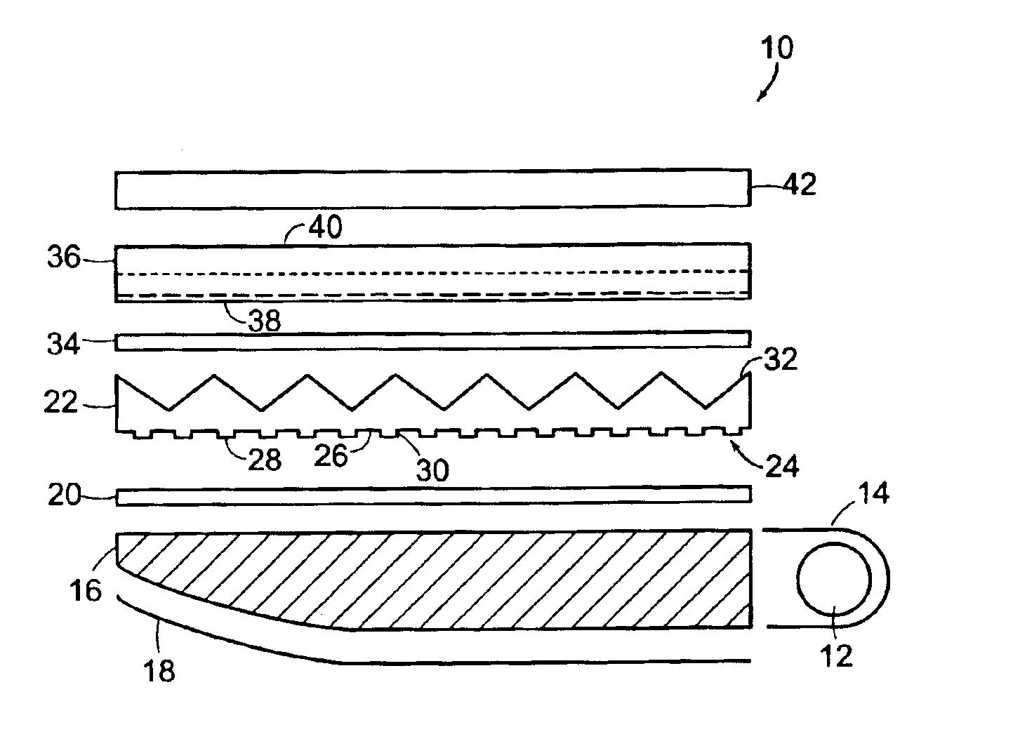
[0018]With respect to the optical performance of a collimating film, it has been found that for individual active matrix liquid crystal display back lighting system designs, the optical efficiency of the particular lamp, waveguide and diffuser system can be improved by designing a collimating film to maximize the use of the diffraction and refraction effects. For example, as shown in FIG. 1, a back lighting system 10 includes a light source 12 and light reflector 14. Light source 12 can be a fluorescent light, incandescent light or other suitable light source. Waveguide 16, which is for directing light out of back lighting system, can be formed of a transparent solid material and is often wedge shaped. On one side of waveguide 16 is waveguide reflector 18 formed of a specular material, such as aluminum or a coated white surface, for reflecting light back to waveguide 16. Waveguide reflector 18 can be curved or flat. Diffuser 20 is a film that diffuses the light from the waveguide in...
PUM
 Abstract
Description
Claims
Application Information