Gearless/oilless gas turbine engine

a gas turbine engine and gearless technology, applied in the direction of machines/engines, bearing unit rigid supports, liquid fuel engines, etc., can solve the problems of reducing the life and reliability of the engine, and reducing the initial and also the initial operating cost. , to achieve the effect of increasing the internal operating pressure and increasing the capacity

Inactive Publication Date: 2005-04-19
HONEYWELL INT INC
View PDF21 Cites 35 Cited by
  • Summary
  • Abstract
  • Description
  • Claims
  • Application Information

AI Technical Summary

Benefits of technology

[0006]In one aspect of the present invention, a rotor comprises at least a first rotor; an air foil bearing supporting a first end of the first rotor; and a hydrodynamic carbon bearing / seal providing additional support to the first rotor and sealing a bearing compartment of the air foil bearing, thereby allowing an increased internal operating pressure, and hence, increased capacity, as compared to the air foil bearing without the hydrodynamic carbon bearing / seal.

Problems solved by technology

Controls and accessories that support critical engine operation, such as the fuel and lubrication systems, cannot operate at the high shaft speeds and, therefore, must be geared down using complex mechanical gear trains.
These conventional engine configurations are complex and result in high initial as well as high operational costs.
The air is hot and, although some cooling may take place in the tube 70, the air increases the magnetic bearing operating temperatures, reducing its life and reliability.
The compressor air is piped into air chambers 90 and, due to seal leakage, some of this compressed air may result in a loss to the engine thermodynamic performance.

Method used


Image

  • Gearless/oilless gas turbine engine
  • Gearless/oilless gas turbine engine
  • Gearless/oilless gas turbine engine

Examples


Embodiment Construction

[0016]The following detailed description is of the best currently contemplated modes of carrying out the invention. The description is not to be taken in a limiting sense, but is made merely for the purpose of illustrating the general principles of the invention.

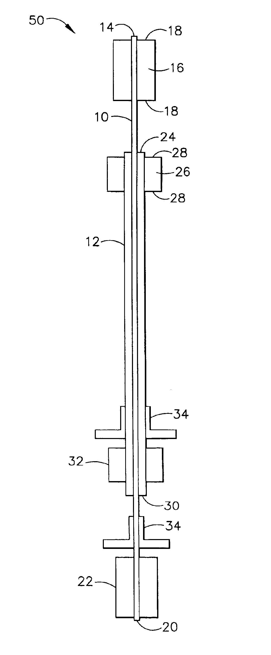
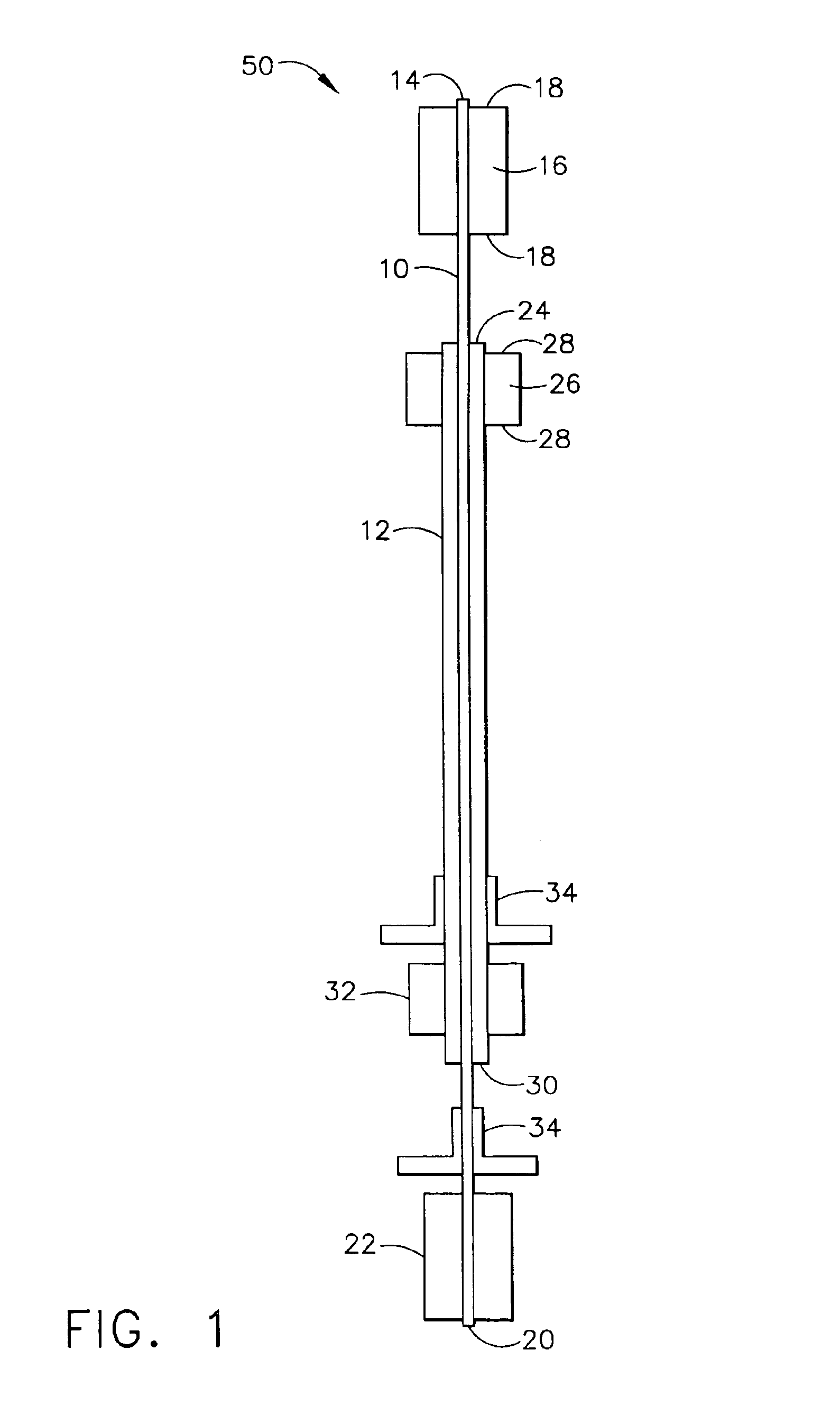
[0017]The present invention eliminates both the complex mechanical gear trains and lubrication systems of the conventional engine configurations by using combinations of hydrodynamic air foil bearings, hydrodynamic solid geometry carbon seals / bearings, magnetic bearings, and electrical starter / generators that can also act as bearings to support the high speed shafts of gas turbine engines. The various bearing types and the starter / generators are arranged in such a way as to share peak loads experienced by the engine shaft during maximum aircraft maneuvers. This results in a smaller bearing and engine size.

[0018]The present invention may use non-contact bearings including air foil, magnetic, and hydrodynamic carbon bearings. ...


PUM


Abstract

The complex mechanical gear trains and lubrication systems of conventional engine configurations are eliminated by using combinations of hydrodynamic air foil bearings, hydrodynamic solid geometry carbon seals/bearings, magnetic bearings, and electrical starter/generators that can also act as bearings to support the high speed shafts of gas turbine engines. The various bearing types and the starter/generators are arranged in such a way as to share peak loads experienced by the engine shaft during maximum aircraft maneuvers. This results in a minimal bearing and engine size.

Description

CROSS-REFERENCE TO RELATED APPLICATION[0001]This application claims the benefit of U.S. Provisional application, Ser. No. 60 / 448,694, filed Feb. 18, 2003.BACKGROUND OF THE INVENTION[0002]The present invention generally relates a gearless and oilless gas turbine engine, and, more specifically, to gearless and oilless rotors supported by several non-contact bearings used in combination with each other.[0003]Conventional aircraft gas turbine engines use a complex oil lubrication system to lubricate rolling element bearings supporting the high speed shafting. Controls and accessories that support critical engine operation, such as the fuel and lubrication systems, cannot operate at the high shaft speeds and, therefore, must be geared down using complex mechanical gear trains. These conventional engine configurations are complex and result in high initial as well as high operational costs.[0004]U.S. Pat. No. 6,367,241 concerns a pressure-assisted electromagnetic thrust bearing. The press...

Claims


Application Information

Patent Timeline
Patent Type & Authority Patents(United States)
IPC IPC(8): F01D25/22F01D25/00F01D25/16F16C33/04F16C33/16F16C27/00F16C27/02F16C17/00F16C17/10F16C17/12
CPCF01D25/16F01D25/166F01D25/22F16C17/024F16C17/10F16C33/16F16C39/063F16C27/02F05D2240/50Y02T50/671F05D2220/766Y02T50/60
Inventor KLAASS, REINHARD M.TAKEUCHI, DONALD I.SCHENK, BJOERN
Owner HONEYWELL INT INC
Why Eureka
Try Eureka