Fixing member for evaporation apparatus

a technology of fixing member and evaporation apparatus, which is applied in the direction of clamping mechanism, vacuum evaporation coating, chemical vapor deposition coating, etc., can solve the problems of not being able to achieve the uniformity required for practical use of organic el displays

Inactive Publication Date: 2005-04-19
SANYO ELECTRIC CO LTD
View PDF11 Cites 85 Cited by
  • Summary
  • Abstract
  • Description
  • Claims
  • Application Information

AI Technical Summary

Benefits of technology

[0013]The present invention therefore provides an evaporation apparatus capable of uniform discharge of a deposition material from each position of an elongated crucible.

Problems solved by technology

Further, because an organic layer is formed between an anode and a cathode, any variation in the thickness of the organic layer has the possibility of creating a display defect such as short-circuit formed between the anode and the cathode.
However, even when a linear source is simply used to form an organic layer or the like using evaporation, the characteristics of the resultant organic EL element significantly vary and it is not possible to realize the uniformity required for practical use of an organic EL display.

Method used


Image

  • Fixing member for evaporation apparatus
  • Fixing member for evaporation apparatus
  • Fixing member for evaporation apparatus

Examples


Embodiment Construction

[0035]A preferred embodiment of the present invention will be described with reference to the drawings.

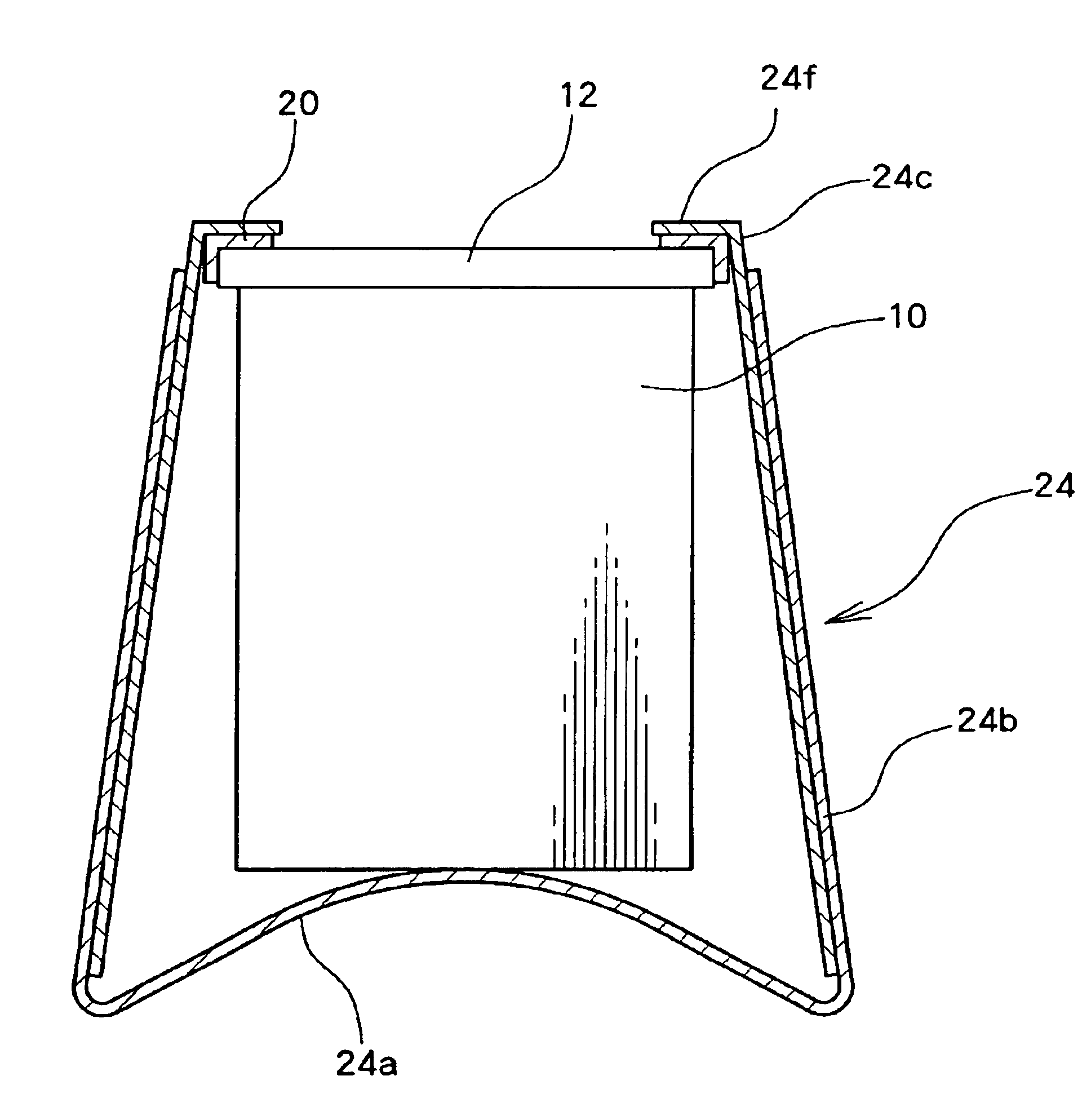
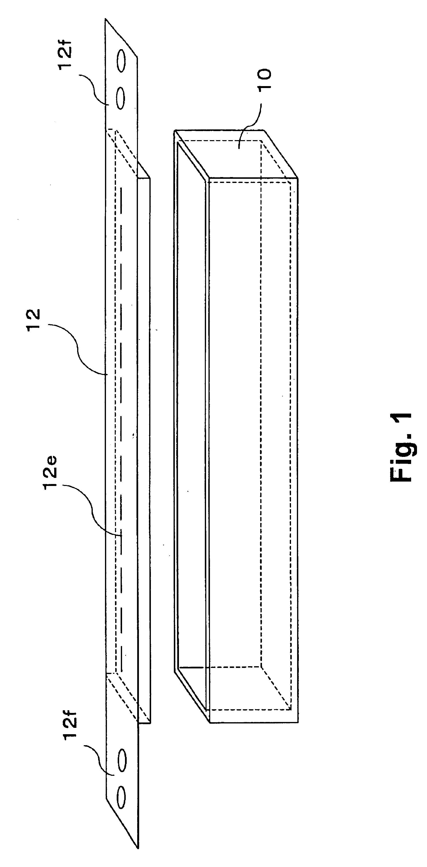
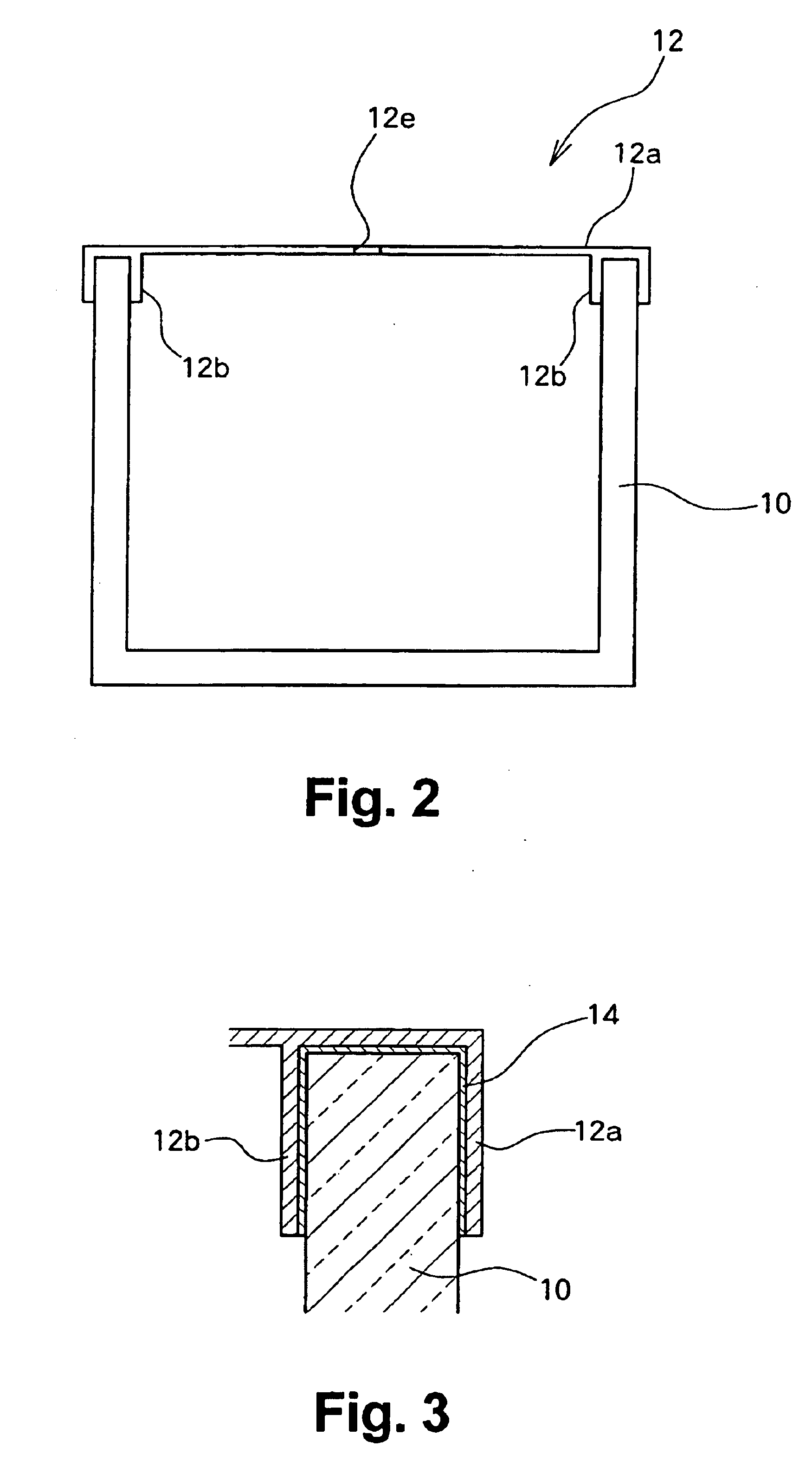
[0036]FIG. 1 shows the structure of an evaporation apparatus according to an embodiment of the present invention. An elongated crucible 10 is a container having an upper opening and storing an evaporation material. The crucible 10 has a roughly rectangular solid shape, and is formed from quartz, for example, with a hollow interior. The crucible 10 may be formed by removing the interior of a bar of quartz, or may be molded. The crucible 10 has a length of about 60 cm, a height of about 4 cm, and width of about 4 cm, for example, but the size may be determined in accordance with the size of the deposition target, such as an organic EL substrate.

[0037]The upper potion of the crucible 10 is covered with and sealed by an electric heater 12. The electric heater 12 is formed of tantalum (Ta), for example, and generates heat when electric current flows from a power source which is connecte...


PUM

PropertyMeasurementUnit
widthaaaaaaaaaa
heightaaaaaaaaaa
thicknessaaaaaaaaaa

Abstract

An electric heater is placed so as to cover an upper opening of a crucible. Then, a plurality of angle members are disposed along the side portions of the electric heater and are pressed and fixed by clamps. The clamp includes, at its bottom, a curved portion formed by bending a plate-like spring member into a convex shape, and generates pressing force between the curved portion and corresponding claw portions at the upper edge, thereby clamping the crucible.

Description

CROSS-REFERENCE TO RELATED APPLICATIONS[0001]The Japanese priority applications Numbers 2003-130708 and 2004-111439 upon which this patent application is based are hereby incorporated by reference.BACKGROUND OF THE INVENTION[0002]1. Field of the Invention[0003]The present invention relates to a fixing member for an evaporation apparatus which heats and evaporates an evaporation material.[0004]2. Description of Related Art[0005]Conventionally, evaporation (in particular, vacuum evaporation) has been used widely for formation of thin films made of various materials. For example, in organic electroluminescence (hereinafter abbreviated as “EL”) displays, which have attracted attention as a possible replacement for liquid crystal displays and which have been developed for practical use, vacuum evaporation is commonly used for forming an organic thin film and a metal electrode layer used in an emissive layer of an organic EL element of such a display panel.[0006]A vacuum evaporation appar...

Claims


Application Information

Patent Timeline
Patent Type & Authority Patents(United States)
IPC IPC(8): C23C14/24H05B33/10H01L51/50
CPCC23C14/243Y10T24/44641Y10T24/44855Y10T117/10Y10T24/44769B60K15/05B60K2015/053
Inventor OCHIAI, MASATOSHIIWASE, HIROTOSHIKATO, SEIZOENDO, TETSURO
Owner SANYO ELECTRIC CO LTD
Why Eureka
Try Eureka