Heated and cooled vacuum chamber shield

Inactive Publication Date: 2005-04-19
APPLIED KOMATSU TECH
View PDF10 Cites 39 Cited by
  • Summary
  • Abstract
  • Description
  • Claims
  • Application Information

AI Technical Summary

Problems solved by technology

These can contaminate and destroy the substrate being processed.
When such particulates (also known as “free” particulates) land on the substrate being processed, they can contaminate a small area of the substrate.
However, when a large substrate is intended for subsequent use as a single item, e.g. as a flat panel display, one defect causes the whole unit to be rejected.
Incomplete or defective chamber cleaning allows particulates to remain in the chamber and cause contamination.
Even when the processing chamber is clean, contaminants can be generated during the sputtering process.
Such specks can create defects which cause rejection of the substrate.
Arcing between adjacent pieces causes a severe localized temperature spike which in most cases releases molecules of one or both of the materials between which the spark arcs.
At worst, when a particulate is a foreign material, the substrate will be contaminated and will have to be rejected.
This may cause some various problems.
The tolerances of the components may

Method used


Image

  • Heated and cooled vacuum chamber shield
  • Heated and cooled vacuum chamber shield
  • Heated and cooled vacuum chamber shield

Examples


Embodiment Construction

)

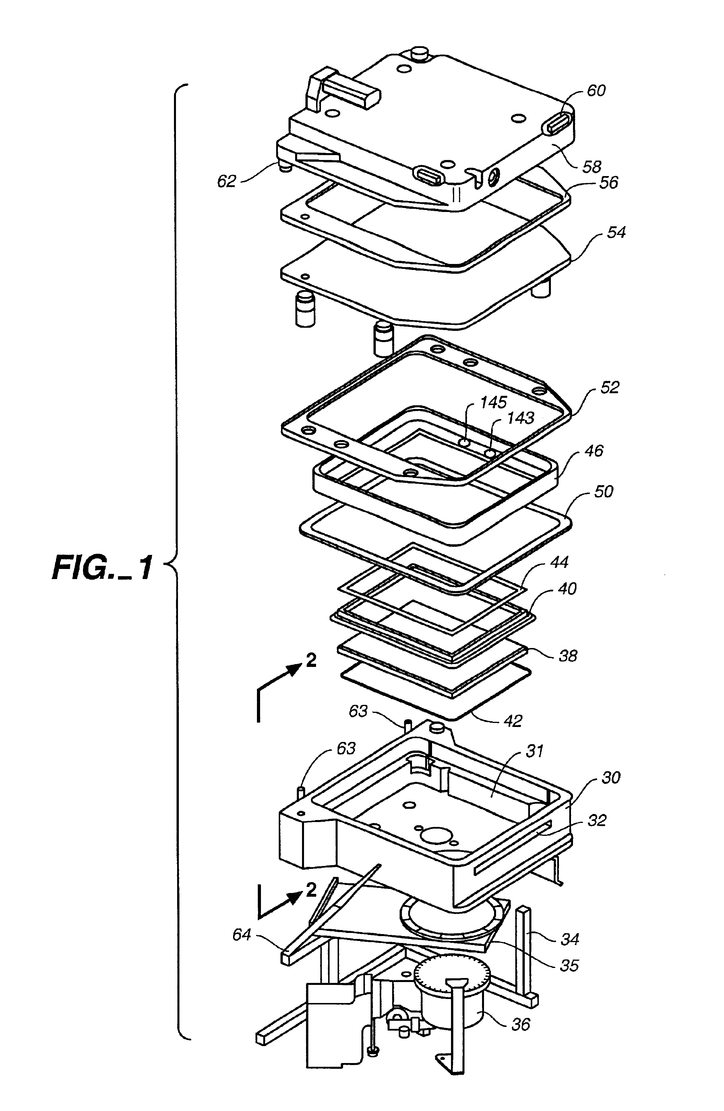
[0030]FIG. 1 shows an exploded view of the pieces which are generally associated with a PVD sputtering processing chamber. More details are presented in U.S. Pat. Nos. 5,487,822, 5,336,585 and 5,362,526 all of which are owned by the assignee of the present application and are incorporated herein by reference in their entirety.

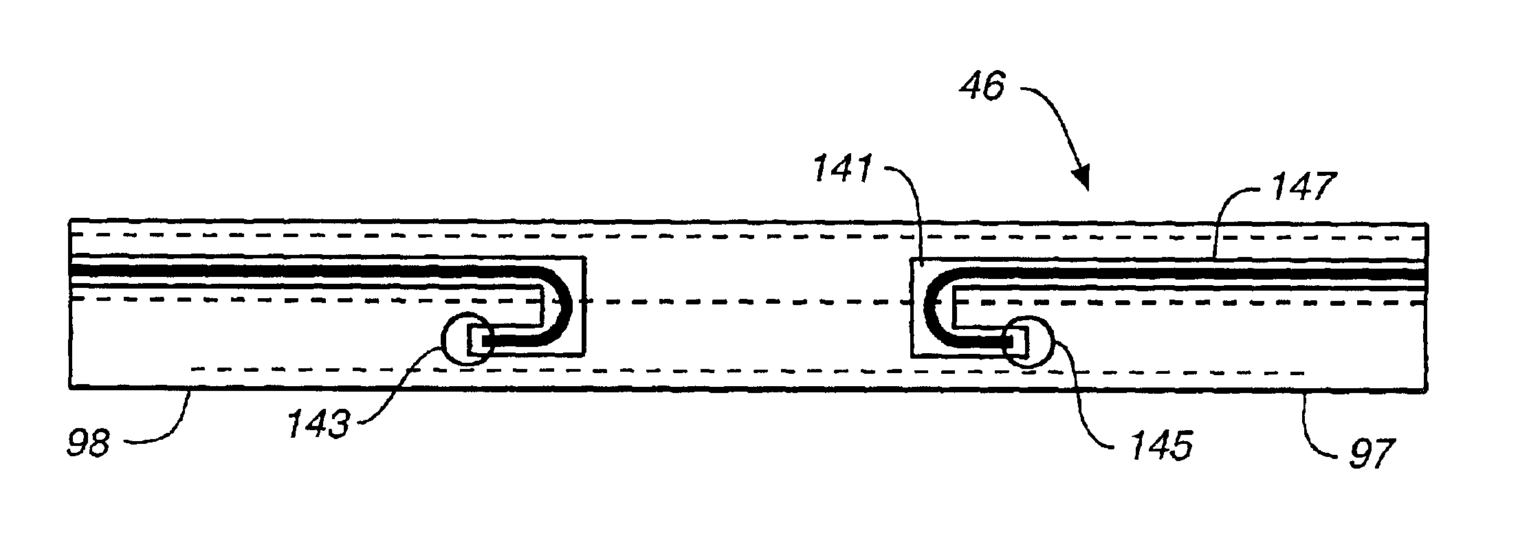
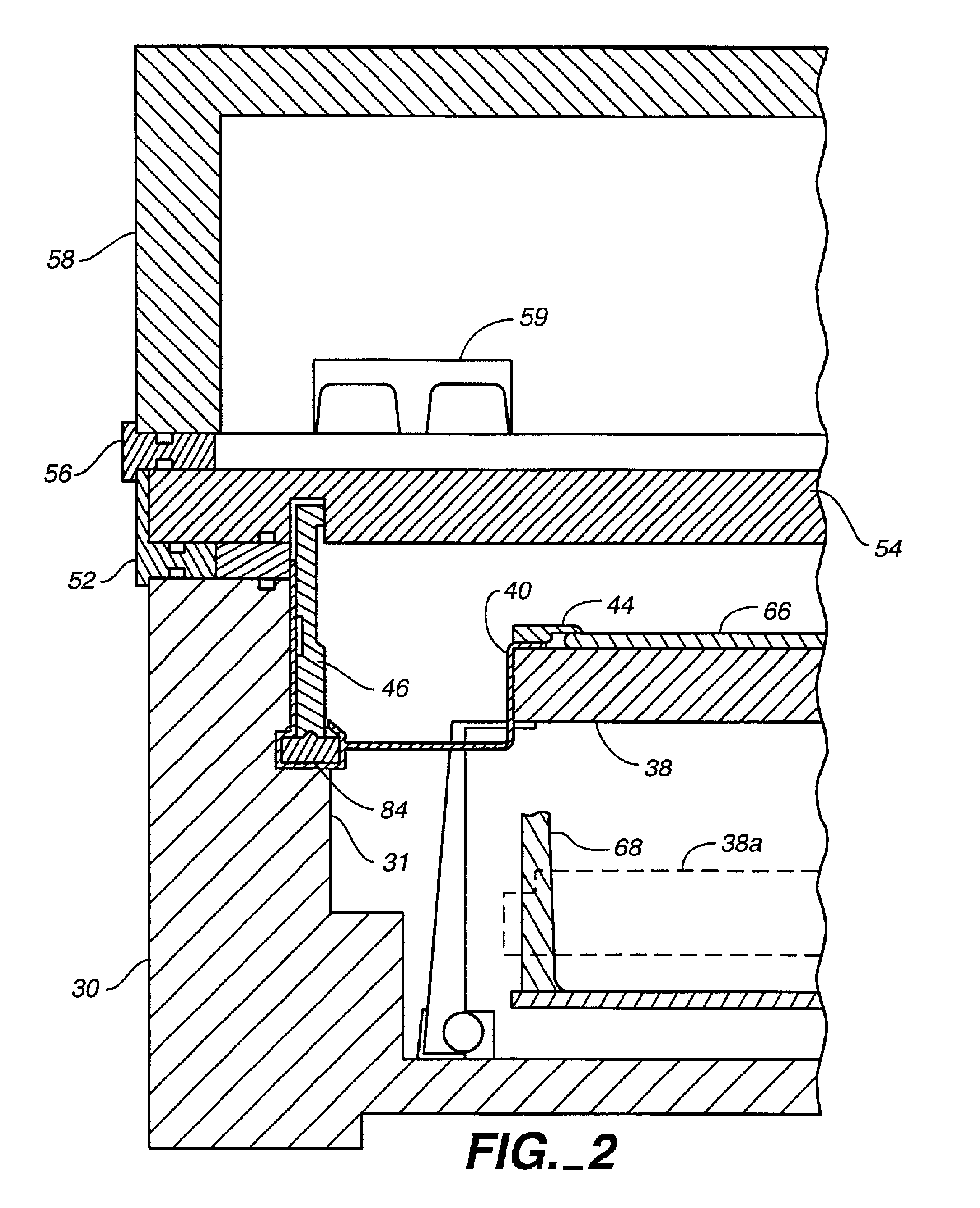
[0031]A processing chamber 30 having an inside processing chamber wall 31 and a slit valve 32 is supported on a frame 34 leading to a gate valve 35 and a cryogenic vacuum pump assembly 36. Processing chamber 30 contains a susceptor or sputtering pedestal 38 supported above a fin plate 42. Sputtering pedestal 38 is surrounded by a sputtering pedestal apron 40. A substrate (not shown in FIG. 1) may be supported on sputtering pedestal 38. A shadow frame 44 covers the edges of the substrate during processing to prevent sputter-deposited material from depositing at the edge and on the back side of the substrate. The substrate is supported on susceptor pedestal 3B f...


PUM

PropertyMeasurementUnit
Temperatureaaaaaaaaaa
Electrical conductoraaaaaaaaaa
Heataaaaaaaaaa

Abstract

The invention is directed to an apparatus and method for reducing particulates in a semiconductor processing chamber. The apparatus comprises a shield for lining at portion of the interior of a vacuum processing chamber. The interior of the shield defines a shield passage. A heater element is disposed within the shield passage. A gas inlet is used for providing gases to the interior of the shield passage. The range of temperatures which may be used is wide and generally fitted to the process. For example, the invention may be used to provide a rapid cooldown or bakeout. Once the temperature is chosen, isothermal conditions can be maintained so as to minimize the thermal cycle stress, reducing cracking, peeling, etc.

Description

[0001]This application is a divisional of application Ser. No. 09 / 328,503, filed Jan. 9, 1998, now U.S. Pat. No. 6,432,203, issued Aug. 13, 2002, and entitled “Heated and cooled vacuum chamber shield,” which is a continuation of application Ser. No. 08 / 819,599, filed Mar. 17, 1997, now abandoned.BACKGROUND OF THE INVENTION[0002]The present invention is directed to a method and apparatus for reducing particulates in processing chambers, and more particularly to a method and apparatus for rapidly heating and cooling a vacuum chamber shield.[0003]In substrate processing in general and in physical vapor deposition (PVD) processes such as sputtering in particular, particulates are present and are generated in the processing chamber. These can contaminate and destroy the substrate being processed. When such particulates (also known as “free” particulates) land on the substrate being processed, they can contaminate a small area of the substrate. If the substrate is die cut into separate ch...

Claims


Application Information

Patent Timeline
IPC IPC(8): C23C14/56H01L21/00C23C14/00C23C14/34H01L21/203
CPCH01L21/67109C23C14/564H01L21/20
Inventor BLACK, RUSSELLTURNER, NORMAN L.DEMARAY, ERNEST
Owner APPLIED KOMATSU TECH
Why Eureka
Try Eureka