
Method for recycling of oil based drilling fluid contaminated with water and water contaminated with oil based drilling fluid

a technology of oil based drilling fluid and recycling method, which is applied in the direction of sedimentation settling tank, borehole/well accessories, treatment water, etc., can solve the problem of not being able to directly discharge, the ratio of oleaginous fluid to non-oleaginous fluid is less than optimal, and the use of emulsion breakers and surface tension breakers that are not environmentally friendly

Inactive Publication Date: 2005-04-19
MI
View PDF19 Cites 63 Cited by
  • Summary
  • Abstract
  • Description
  • Claims
  • Application Information

AI Technical Summary

Problems solved by technology

During the drilling process, it is not uncommon for the drilling fluid to encounter a water bearing formation and thus the ratio of oleaginous fluid to non-oleaginous fluid is less than optimal.
One of the primary difficulties with this system is the use of emulsion breakers and surface tension breakers that are not environmentally friendly.
That is to say the emulsion breakers and surface tension breakers of the prior art are harmful to aquatic life and thus may not be directly discharged without further treatment or disposal.

Method used


Image

  • Method for recycling of oil based drilling fluid contaminated with water and water contaminated with oil based drilling fluid
  • Method for recycling of oil based drilling fluid contaminated with water and water contaminated with oil based drilling fluid
  • Method for recycling of oil based drilling fluid contaminated with water and water contaminated with oil based drilling fluid

Examples


example 1

[0041]The basic test emulsion material utilised the following laboratory tests are drilling fluids as substantially described above with an Oil / Water Ratio (OWR) of approximately 32 / 68 and OWR 50 / 50.

[0042]

Test FluidSlop 31 / 69Slop 50 / 50Density (at RT) 1.211.18OWR31 / 6950 / 50Dry Material % wt10  10-15

[0043]Emulsion Clearance Agent: The emulsion clearance agents of the prior art serve as basis and standard for this test. At the same time it is about an industrial flushing agent based on anionic surfactants (RENAX) and a surfactant raw material based on sugar surfactants (6202), being applied as follows: Renax+Sugar surfactant 6202, Concentration: 2% each, Ratio of mixture: 1:1. A variety of Emulsion Clearance Agents (ECA) were tested as shown below:

[0044]

ECAWigol Art. No.PH-ValueBasisEMD,0013557.5Anionic SurfactantEMD 2 + 2,0013577.5Anionic SurfactantSugar SurfactantEMD 8.23.0Anionic SurfactantNon-ionic SurfactantSugar SurfactantEMD 8.63.0Anionic SurfactantNon-ionic SurfactantSugar Surfa...


PUM

PropertyMeasurementUnit
Fractionaaaaaaaaaa
Fractionaaaaaaaaaa
Timeaaaaaaaaaa

Abstract

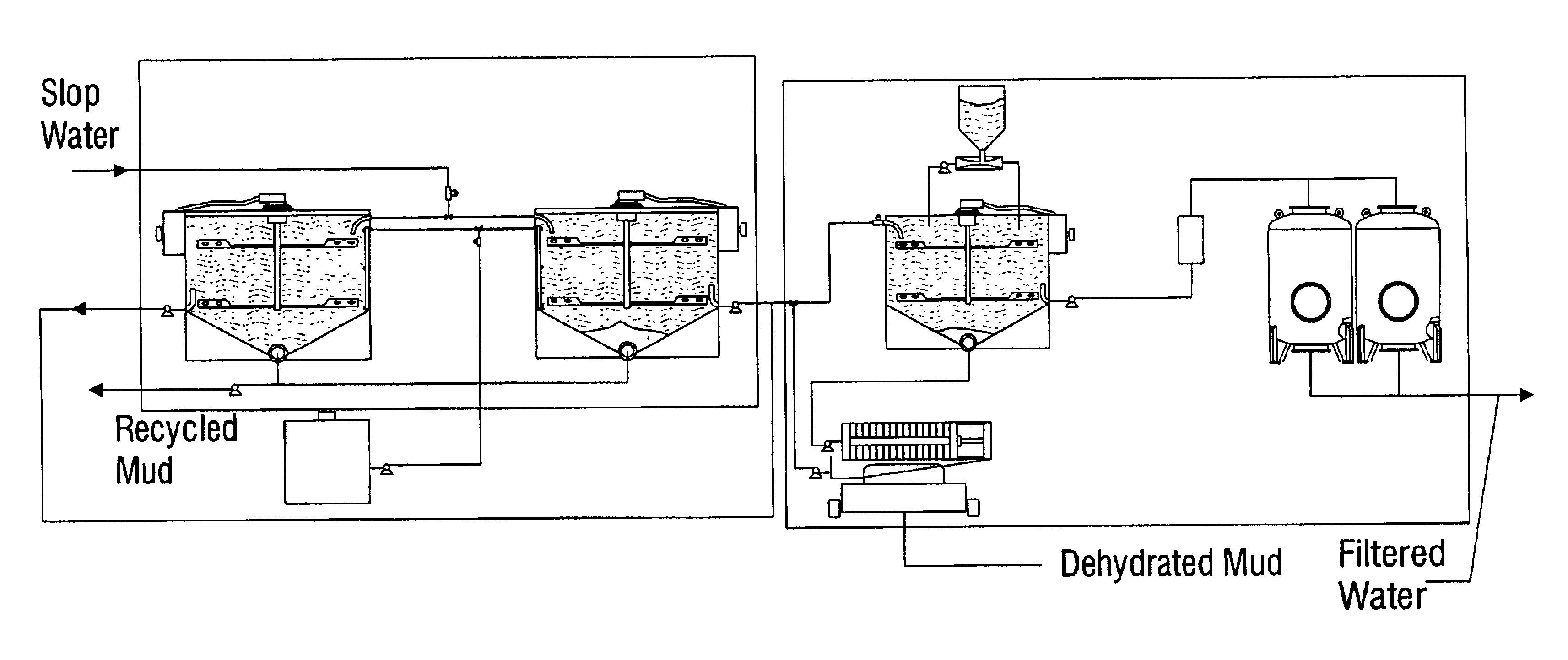
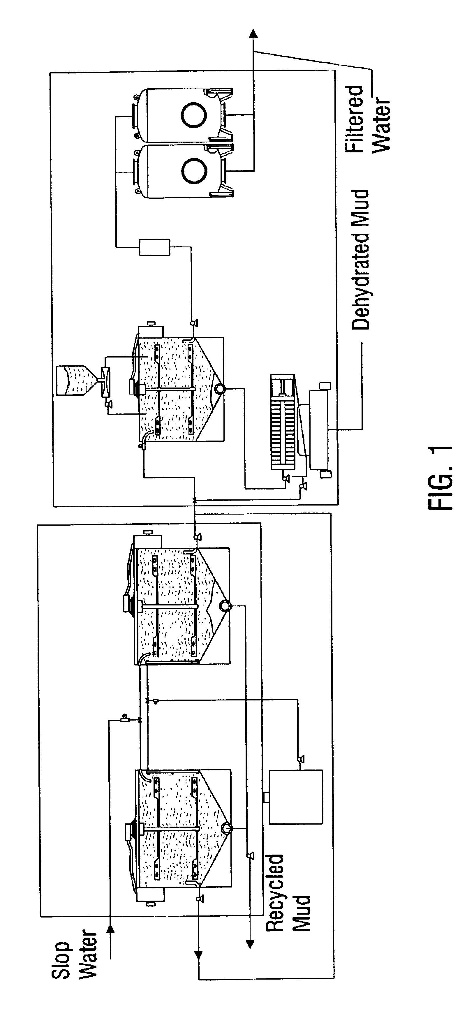
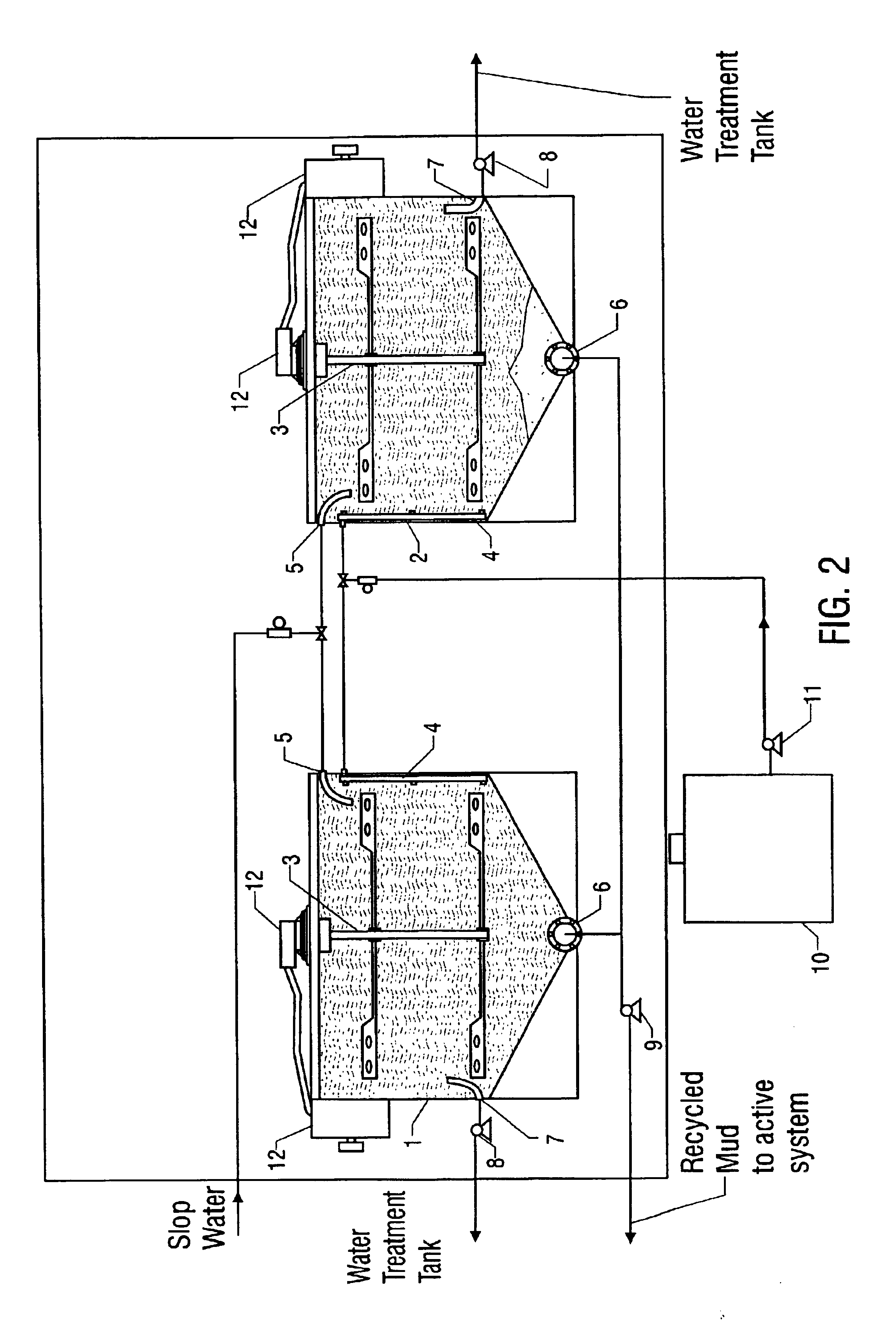
A mobile apparatus and method for recycling an invert emulsion based drilling fluid, in which the invert emulsion based drilling fluid includes an oleaginous component and an aqueous component. The apparatus includes an emulsion breaking tank, a water treatment tank, a filter press, and hydrocarbon filters. The method includes: mixing said invert emulsion drilling fluid with a emulsion breaker, wherein the emulsion breaker is a mixture of an alkyl glucoside and an alkane sulfonate; and separating the oleaginous component of the invert emulsion drilling fluid from the aqueous component of the invert emulsion drilling fluid. The method preferably utilizes an emulsion breaker that is a combination of an anionic surfactant, a nonionic surfactant and an alkyl polyglycoside surfactant.

Description

BACKGROUND[0001]Invert emulsion fluids, i.e. emulsions in which the non-oleaginous fluid is the discontinuous phase and the oleaginous fluid is the continuous phase, are employed in drilling processes for the development of oil or gas sources, as well as, in geothermal drilling, water drilling, geoscientific drilling and mine drilling. Specifically, the invert emulsion fluids are conventionally utilized for such purposes as providing stability to the drilled hole, forming a thin filter cake, lubricating the drilling bore and the downhole area and assembly, and penetrating salt beds without sloughing or enlargement of the drilled hole.[0002]Oil-based drilling fluids are generally used in the form of invert emulsion muds. An invert emulsion mud consists of three-phases: an oleaginous phase, a non-oleaginous phase and a finely divided particle phase. Also typically included are emulsifiers and emulsifier systems, weighting agents, fluid loss additives, viscosity regulators and the like...

Claims


Application Information

Patent Timeline
IPC IPC(8): B01D17/00B01D21/00B01D17/02C02F9/00C02F1/68C10G33/00C10G33/06E21B21/06E21B21/00C02F1/52B01D17/05C10G33/04
CPCB01D17/00B01D17/0208B01D17/047B01D21/0012B01D21/01B01D21/02B01D21/04B01D21/186C02F1/682C02F9/00C09K8/36C10G33/04C10G33/06E21B21/063E21B21/068B01D17/0202B01D17/0217B01D17/02B01D17/0214B01D17/041C10G2300/4081C02F1/001C02F1/40C02F1/52C02F1/5236C02F11/121C02F2101/20C02F2101/325C02F2103/008C02F2103/10C02F2303/16C02F2305/04C02F2305/12C10G2300/1055C10G2300/1011C02F1/68Y02P30/20
Inventor MUELLER, FRANK MANFRED FRANZ
Owner MI
Learn More