
Method for separating fluids

a technology of fluid separation and separation method, which is applied in the direction of separation process, other chemical processes, borehole/well accessories, etc., can solve the problems of high risk of acid corrosion of pipelines under the sea, large equipment footprint (physical size), and high cost of oil and gas lost in flaring, so as to accelerate the breaking of emulsions, reduce the oil content, and avoid the effect of gas phase flotation

Inactive Publication Date: 2006-01-24
SCHLUMBERGER TECH CORP
View PDF16 Cites 39 Cited by
  • Summary
  • Abstract
  • Description
  • Claims
  • Application Information

AI Technical Summary

Benefits of technology

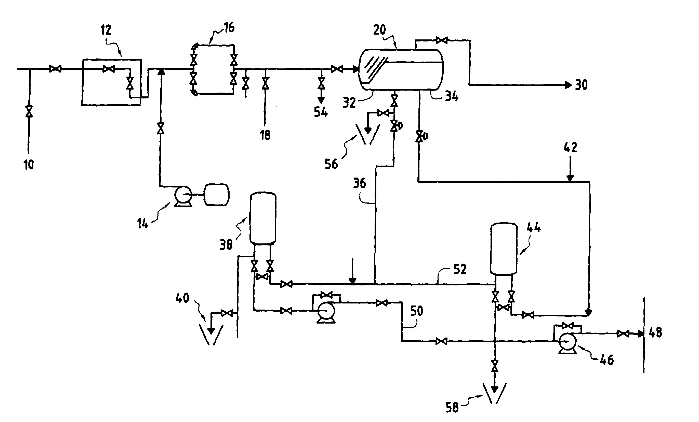
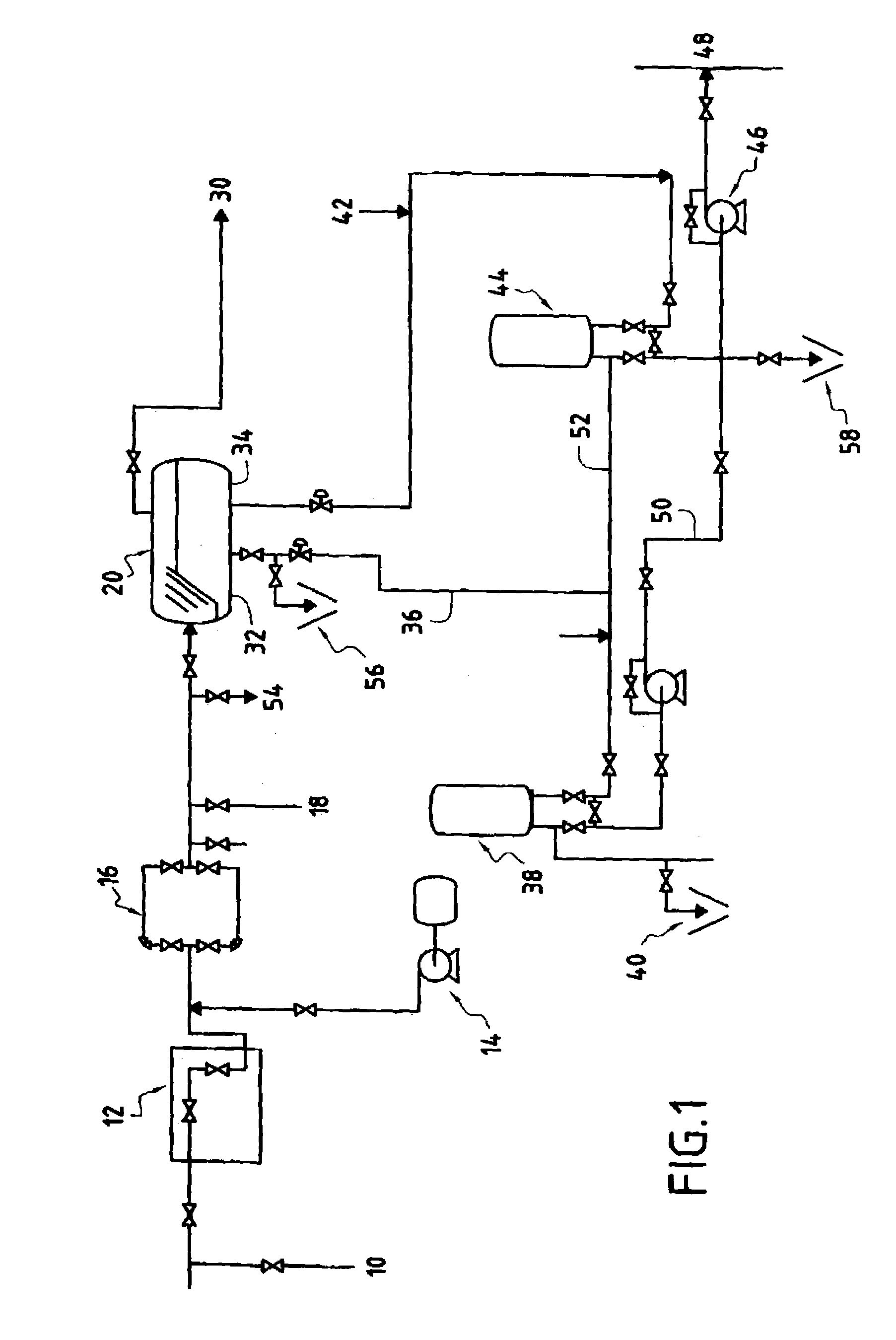
[0012]2. Use of optimized emulsion breakers in a phase separator, selected for best results with the fluids produced by the well, to accelerate the separation of oil from the fluids, and to lower the residual oil content in the fluids to levels compatible with environmental regulations; and
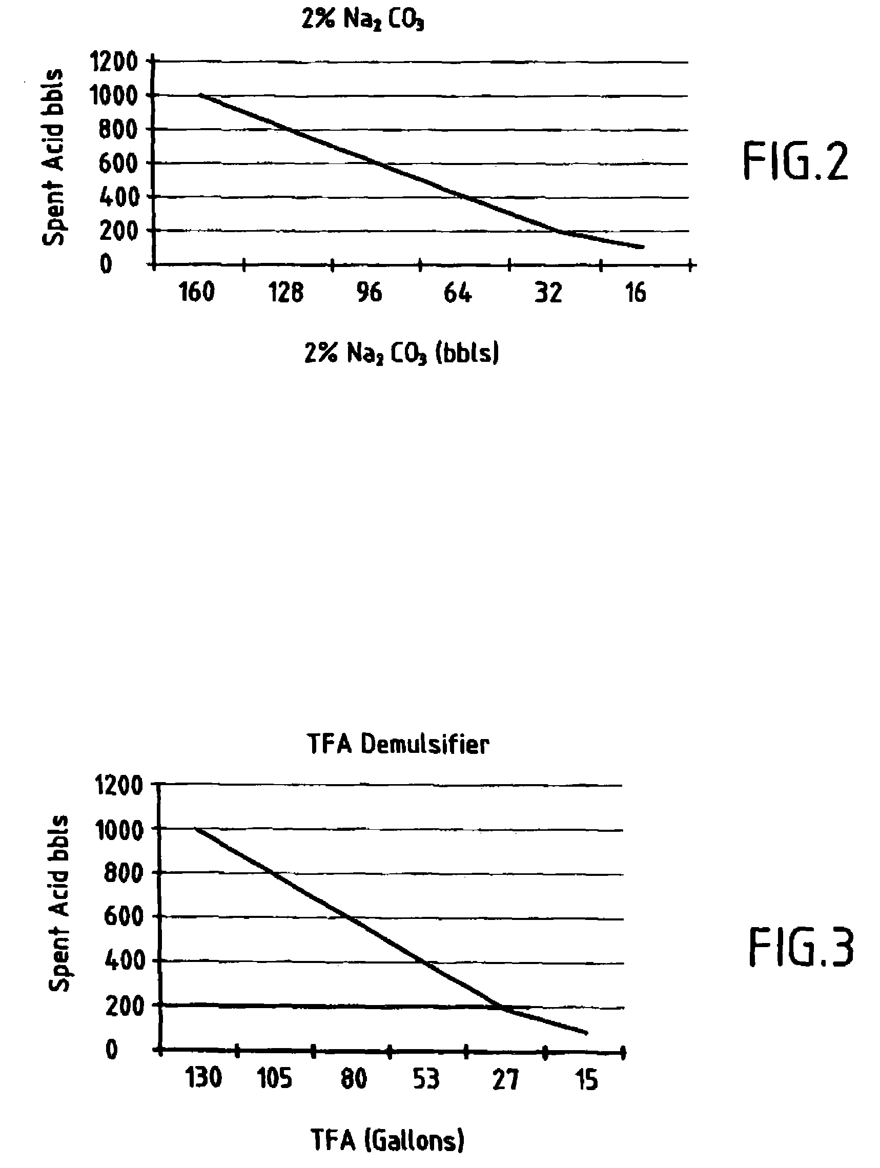
[0015]A blended surfactant demulsifier can be used to maximize the efficiency of the separation of oil from the fluids. The use of a non-toxic demulsifier for the separation of oil from the fluids is preferred.

Problems solved by technology

The hydrocarbon burning produces toxic gases, soot, acid rain, unburned hydrocarbons and a large amount of CO2, all of which are detrimental to the environment.
The direct economic impact is the cost of the oil and gas lost in flaring as well as the cost of burning equipment.
This equipment has a large footprint (physical size), cost, power consumption and noise.
Moreover, the risk of acid corrosion of pipelines under the sea is high.
Any pipeline leak resulting from corrosion can potentially cause a shut down of production for several weeks as well as high repair costs and major pollution.
Indirect costs linked to the large liability exposure due to the potential and actual damage to the environment are difficult to evaluate but could be several order of magnitude larger than direct costs.

Method used


Image

  • Method for separating fluids
  • Method for separating fluids
  • Method for separating fluids

Examples


Embodiment Construction

I—Testing Pumps, Separator, Skimmer & Surge Tank

[0020]To achieve the aims of the invention, it is necessary to re-inject oil into the production line after spent acid is cleaned out. In order to achieve this, units for pumping live oil from the separator or surge tank are necessary to overcome the pressure in the production line especially at the start of the clean-up operation. It is also useful to have these pumps in order to achieve representative data during production well testing where it is required to have a relatively low separator pressure (to respect the choke performance / critical flow condition where downstream pressure should be 50% less than the upstream pressure).

[0021]Traditional three-phase separators work on the principle of gravity force settling and difference in gravity between the phases and the retention time of mixture. For oil and water production at 5000 bbls / day retention time in the separator is typically around 2 minutes, which can be less than the preci...


PUM

PropertyMeasurementUnit
Fractionaaaaaaaaaa
Fractionaaaaaaaaaa
Fractionaaaaaaaaaa

Abstract

Methods of treatment of fluids produced by an oil or gas well following a stimulation operation, allowing separation from the fluids and re-injection of oil and gas hydrocarbons in a production pipeline under pressure, and allowing achievement of suitable quality for the residual fluids compatible with their rejection, for example into the sea, including the following three elements; neutralization of the fluids by mixing with a high pH chemical, until the resulting pH reaches a level compatible with the equipment and pipes; use of optimized emulsion breakers in a phase separator, selected for best results with the fluids produced by the well, to accelerate the separation of oil from the fluids, and to lower the residual oil content in the fluids to levels compatible with environmental regulations; and use of a multi-phase pump to pump the oil and gas hydrocarbons produced and reinject them in a pipeline under pressure.

Description

[0001]This application claims benefit of Application No. 60 / 239,970, filed Oct. 13, 2000.FIELD OF THE INVENTION[0002]The present invention relates to the separation and testing of fluids obtained from underground formations. In particular, the invention provides new techniques for the separation of fluids from subterranean hydrocarbon wells, which are especially applicable in offshore situations.BACKGROUND[0003]The invention provides new solutions to address certain major environmental problems typically encountered in hydrocarbon exploration and production wells, especially in offshore operations. A common practice in certain regions (for example the Middle East) is to stimulate drain holes in carbonate reservoirs with hydrochloric acid, and then clean up the well before connecting it to the production line. One previous approach has been to direct clean up fluids through a burner until the pH falls to less than 6, burning all hydrocarbons produced and dumping the spent acid and co...

Claims


Application Information

Patent Timeline
IPC IPC(8): B01D17/05B01D17/00B01D17/025B01D19/00E21B43/34
CPCB01D17/00B01D19/0068E21B43/34B01D17/0208B01D17/0217B01D17/047
Inventor MOHSEN, ABDUL HAMEEDNASHAT, MOHAMMEDSHAHEEN, MANSOURTENGIRSEK, ALPWILSON, THOMAS
Owner SCHLUMBERGER TECH CORP
Learn More