Multi conductor arrangement for transferring energy and/or data

a multi-conductor, energy-transfer technology, applied in the direction of insulated conductors, power cables, cables, etc., can solve the problems of complex contact-making mechanisms that have to be designed and provided, time-consuming contact-making process, and product stiffness, so as to simplify the laying of the bus system, reduce the effect of stiffness and speed up the production speed

Inactive Publication Date: 2005-04-19
SIEMENS AG
View PDF12 Cites 8 Cited by
  • Summary
  • Abstract
  • Description
  • Claims
  • Application Information

AI Technical Summary

Benefits of technology

[0015]The advantages which are associated with this refinement of the multiconductor arrangement are, in particular, that designing a bus system (power bus/data bus) with thin-layer insulation and with a round structure considerably simplifies the laying of the bus system. Instead of complex slotted apertures in masonry or complicated plug-in systems in switchgear cabinets, the new multiconductor arrangement can now be laid through simple round holes, which can be produced quickly. In this case, the conductor arrangement is easy to lay, in a similar manner to a normal round cable. Since the multiconductor arrangement with a round design is considerably less stiff, relatively small bending radii can be produced during laying work.
[0016]In contrast to the previously used conductor arrangements of a flat type, the embodiment of the arrangement according to the invention using thin layer technology leads to the wall thickness of

Problems solved by technology

However, a configuration such as this for such a multiconductor arrangement results in a number of difficulties:a) the relatively thick walls mean that complex contact-making mechanisms have to be designed and provided.
This leads to a time-consuming contact-making process.
Furthermore, the product is very stiff, w

Method used


Image

  • Multi conductor arrangement for transferring energy and/or data
  • Multi conductor arrangement for transferring energy and/or data
  • Multi conductor arrangement for transferring energy and/or data

Examples


Embodiment Construction

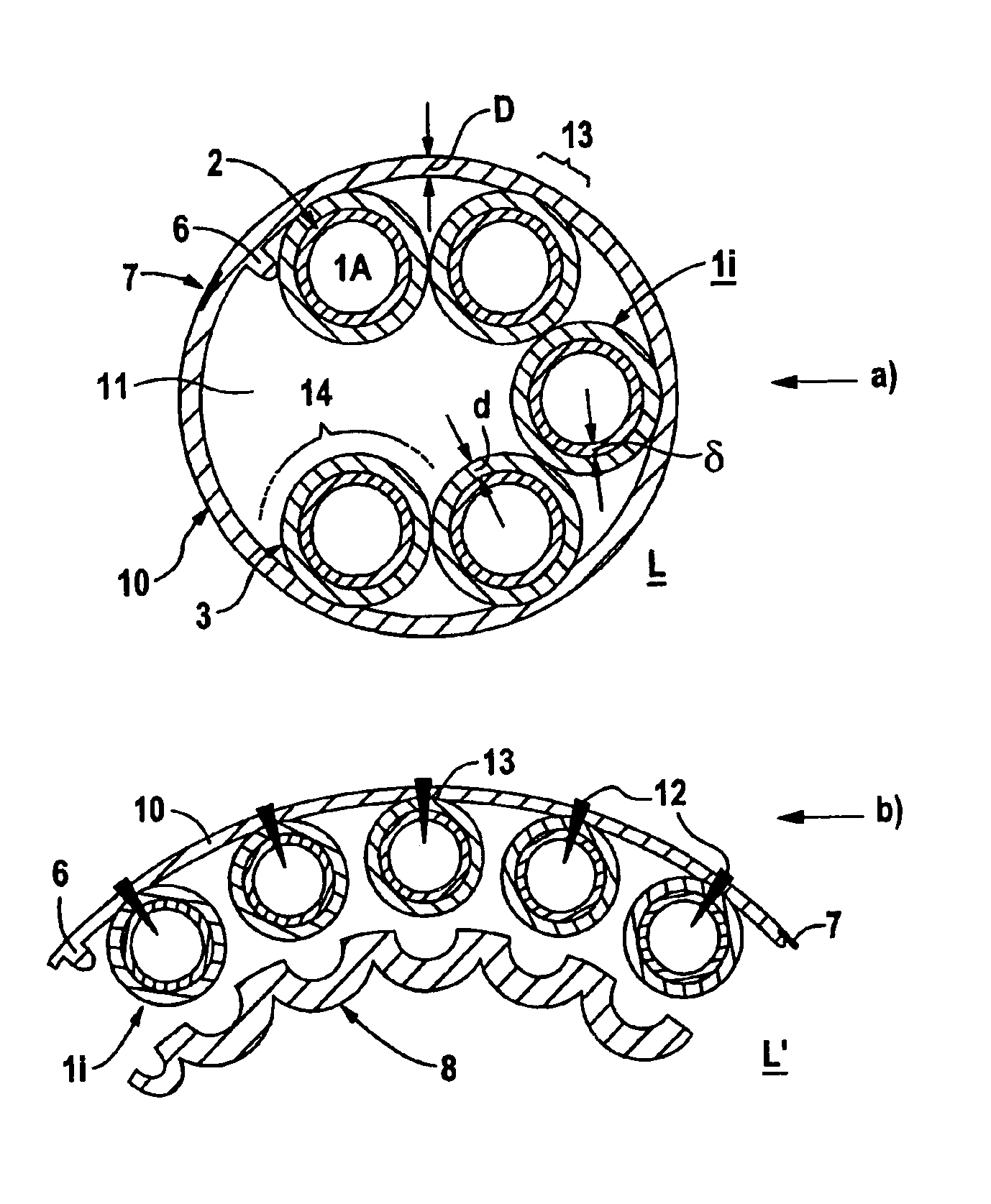
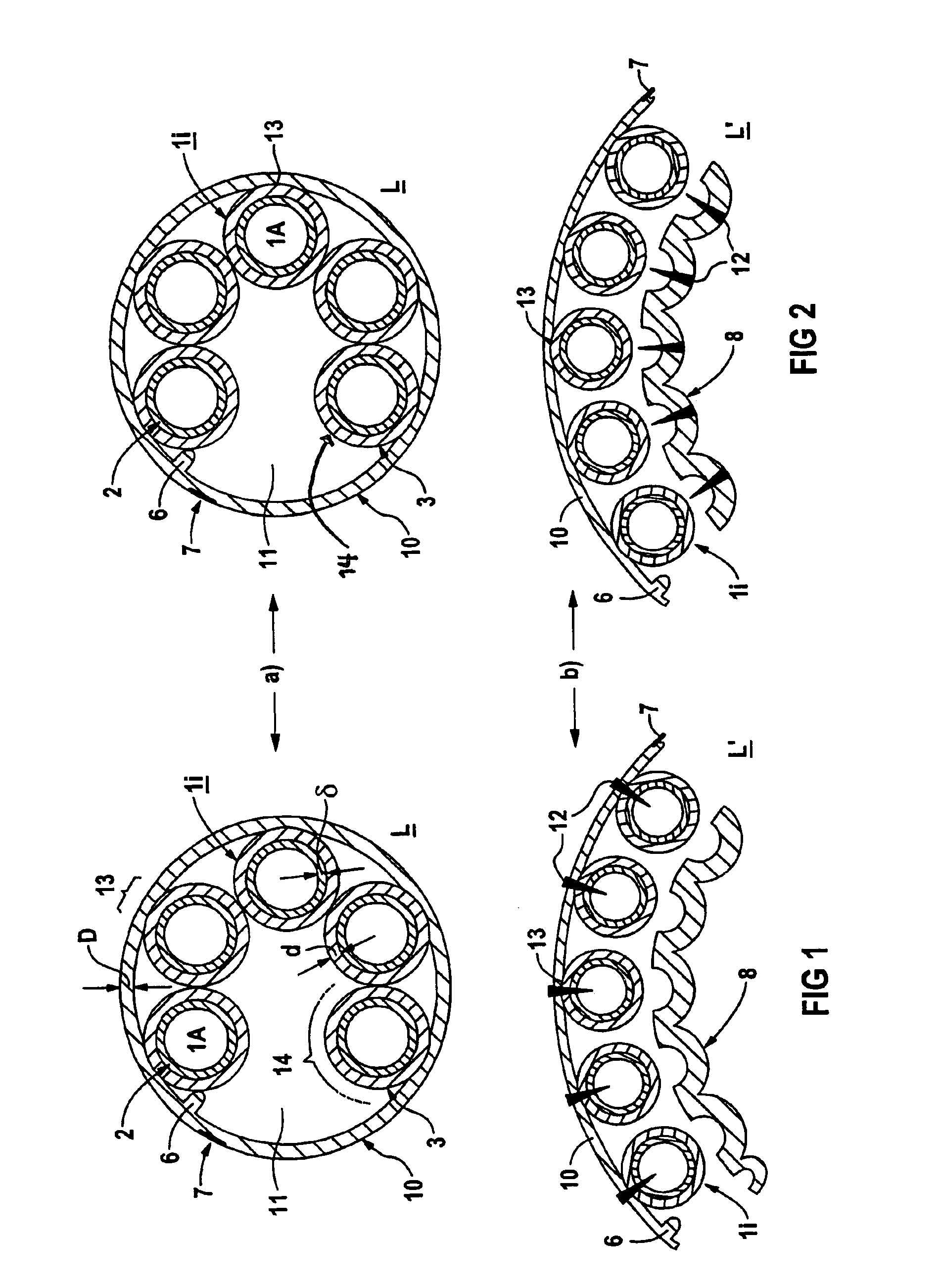
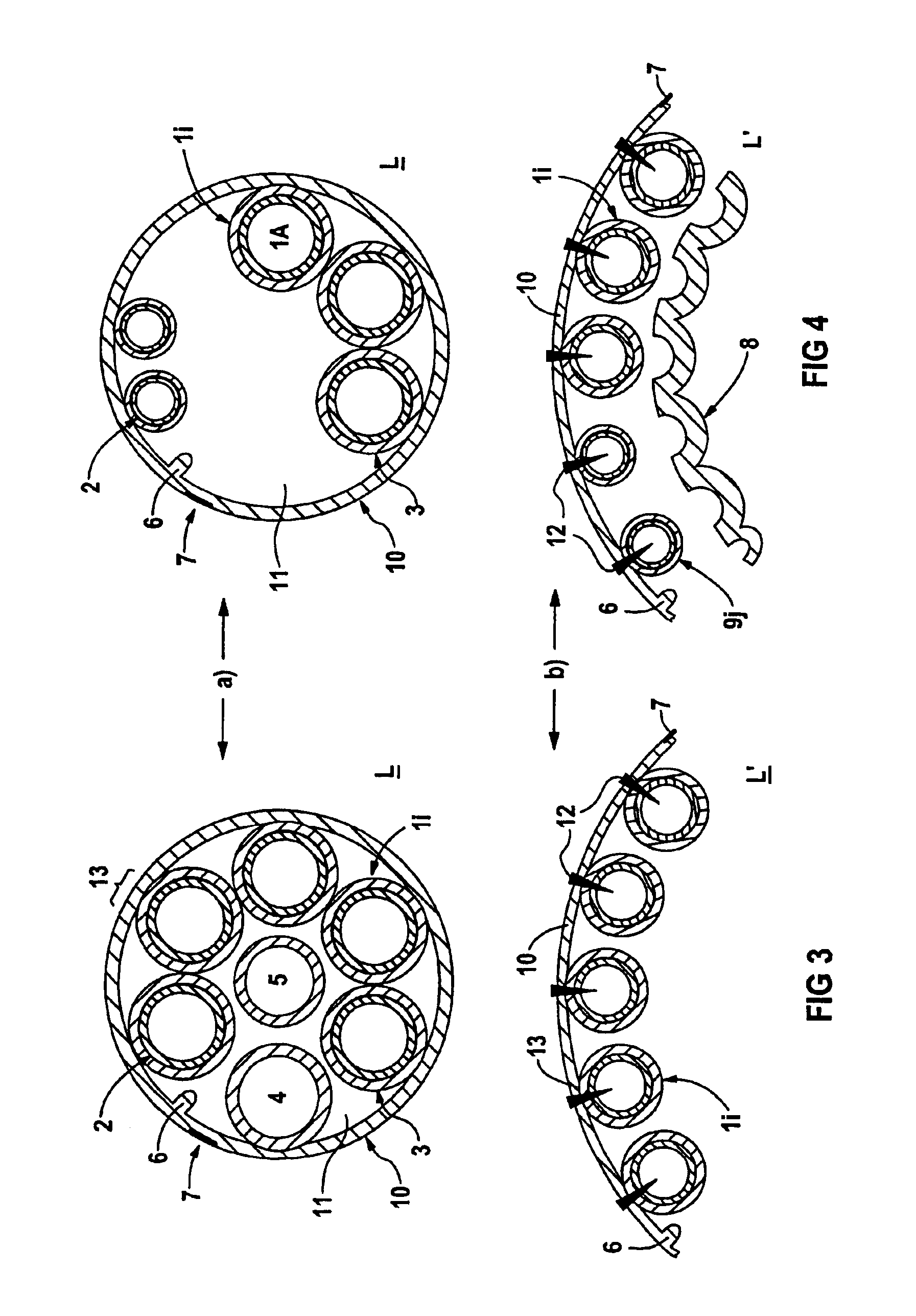
[0046]The parts a in the figures each show the cross section through the multiconductor arrangement, which forms a round conductor, with a closed casing-like support 10, while the parts b of the figures each show, at least partially, the round conductor which is, for example, disconnected in one end area. In this case, a number of conductor elements 1i or 9j are firmly connected on the inside of the support to the casing-like support 10 of the multiconductor arrangements, which are denoted by L in the parts a and by L′ in the parts b. The corresponding fixing is in this case provided between the material of the element sheaths 3 and the material of the support 10. In one preferred embodiment, on which the figures in the following text are based, the support and the sheaths are composed of the same material. The support 10 and the sheaths 3 can advantageously be formed at the same time using this material in a single process step, in particular such as an extrusion step, by means of ...


PUM


Abstract

A multi conductor (L) arrangement for transferring energy and/or data. The system contains a plurality of conductor elements (1i) respectively comprising a conductor (1A) which is surrounded by an insulation (2) and an insulating sleeve (3), the conductor elements being mechanically connected to each other. Elements (12) for contacting the conductive elements are also provided. The system is provided with a flexible tubular or pipe-shaped support (10) made of an insulating material having a maximum thickness (D) of 1 mm, the conductive elements (1I) are arranged on the inside wall of the support, and the insulating sleeves (3) of the conductive elements have a respective thickness (d) which is at the most equal to the thickness (D) of the support. A thermoplastic elastomer is preferably used as an insulating material.

Description

CROSS REFERENCE TO RELATED APPLICATIONS[0001]This is the 35 USC 371 national stage of international application PCT / DE02 / 01392 filed on Apr. 15, 2002, which designated the United States of America.FIELD OF THE INVENTION[0002]The invention relates to a multiconductor arrangement for power and / or data transmission having a number of conductor elements, which each have a metallic conductor core with core insulation and, furthermore, an insulating sheath, and are mechanically connected to one another. Means are also provided for making contact with the conductor elements.BACKGROUND OF THE INVENTION[0003]Conductor arrangements or systems for power transmission and / or for data transmission of a flat type, and which are also referred to as power bus systems or data bus lines, are frequently used nowadays for the electrical connection of various end loads such as motors, actuators, sensors or controllers. These conductor arrangements are normally in the form of multicore / polycore, rubber-in...

Claims


Application Information

Patent Timeline
IPC IPC(8): H01B7/38H01B7/08H01B9/00H01B7/00
CPCH01B7/0892H01B9/003H01B7/38
Inventor GREINER, ROBERTKRESS, TONIOCHSENKUHN, MANFRED
Owner SIEMENS AG
Why Eureka
Try Eureka