Lithography system and method

a technology of lithography and system, applied in the field of lithography system, can solve the problems of poor influence on the stepping accuracy and alignment accuracy of the stage, the damage to the environment, and the affect of magnification control accuracy during the exposure operation

Inactive Publication Date: 2005-04-19
NIKON CORP
View PDF11 Cites 17 Cited by
  • Summary
  • Abstract
  • Description
  • Claims
  • Application Information

AI Technical Summary

Benefits of technology

[0010]An object of the present invention is to provide a lithography system of in-line type in which environmental conditions in an exposure apparatus and in a substrate processing apparatus connected to the exposure apparatus do not badly influence each other.
[0011]Another object of the present invention is to control environment in an exposure apparatus connected to a substrate processing apparatus, with high accuracy.
[0012]A further object of the present invention is to control an environment in a substrate processing apparatus connected to an exposure apparatus, with high accuracy.
[0014]With this arrangement, the environment of at least one of the exposure apparatus and the processing apparatus is measured, and the environment of at least one of the exposure apparatus and the substrate processing apparatus is controlled by the control device on the basis of the measured value given from the environment sensor in such a manner that the environment in the exposure apparatus becomes substantially the same as the environment in the substrate processing apparatus. Thus, even when the substrate is transferred between the exposure apparatus and the substrate processing apparatus, there arises no bad influence between these apparatuses, thereby always processing the substrate correctly in the apparatuses.
[0017]That is to say, the air pressure, temperature and humidity in the apparatus are great influencing factors among environmental conditions affecting an influence between both apparatuses, and, thus, it is more desirable that at least one of the air pressure, temperature and humidity (preferably, all of them) in one apparatus becomes the same as that (or those) in the other apparatus.
[0018]Although the processing apparatus of the lithography system is not limited to a particular processing apparatus so long as it is an apparatus for processing a substrate before exposure or after exposure can be processed. For example, it is desirable that the processing apparatus has at least one of a resist coating function and a developing function. In the apparatus having such resist coating function and developing function, since the environmental conditions such as pressure, temperature and humidity in the apparatus must be controlled precisely, when the control is effected in such a manner that the environmental conditions in both apparatuses become substantially the same, excellent advantages can be achieved.

Problems solved by technology

When the exposure apparatus and the coater / developer are assembled as the in-line system, since there is a problem that a portion (connecting portion) through which the wafer is transferred between both apparatuses is influenced by the chemical environment, the connecting portion is sealingly enclosed by a cover to provide the same environment as those in the chambers of both apparatuses, while isolating the connecting portion from an external clean room environment.
Therefore, the difference in pressure, temperature or / and humidity occurs frequently between both apparatuses, with the result that the environments in both chambers which were controlled with high accuracy affects each other to worsen the environments.
For example, in the exposure apparatus, due to the change in pressure caused by introduction of air from the coater / developer, refractive index of air is forced to change to thereby change the projection magnification of a projection optical system, with the result that the magnification control accuracy during the exposure operation is affected by a bad influence or an air fluctuation due to the change of temperature (the temperature fluctuation) occurs.
As a result, since measurement error is apt to occur in laser interferometers for measuring the position of the wafer, stepping accuracy and alignment accuracy of a stage are affected by a bad influence.
Also if the humidity is changed, since the refractive index is changed, the similar bad influence would occur.
On the other hand, in the coater / developer, while the optimum temperature for development must be maintained, when the air is introduced from the exposure apparatus, the optimum temperature cannot be maintained, whereby developed result would be affected by a bad influence.

Method used


Image

  • Lithography system and method
  • Lithography system and method
  • Lithography system and method

Examples


Embodiment Construction

[0029]Now, a preferred embodiment of the present invention will be explained with reference to the accompanying drawings.

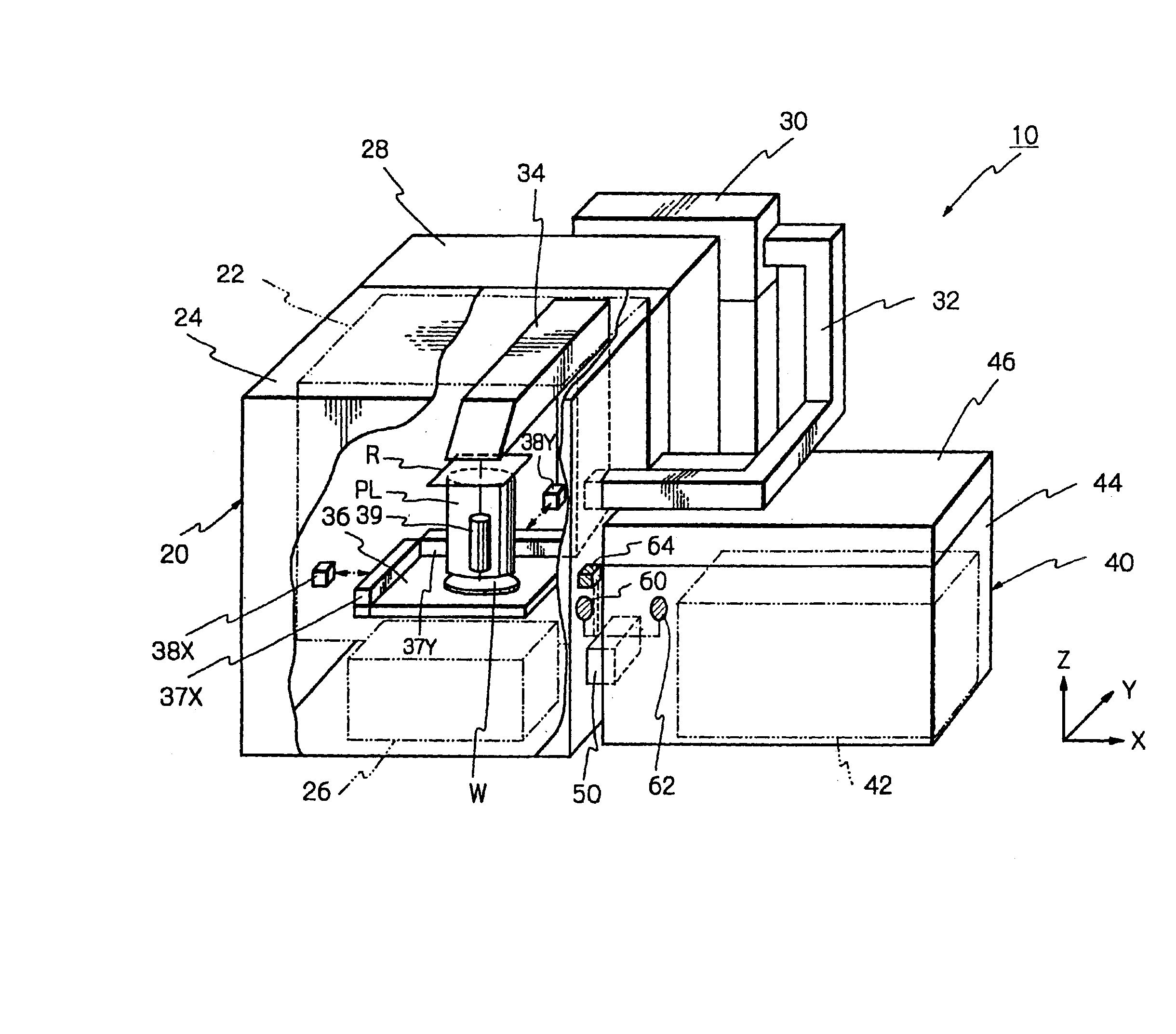
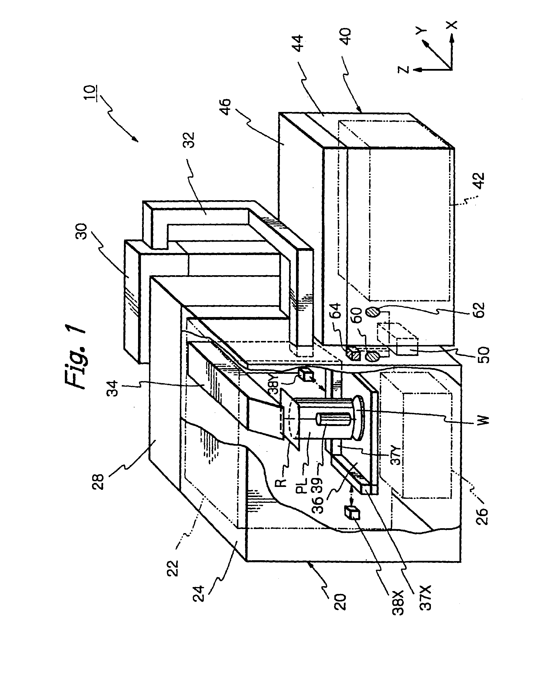
[0030]FIG. 1 is a schematic perspective view of a lithography system according to a preferred embodiment of the present invention.

[0031]The lithography system 10 includes an exposure apparatus 20 for effecting exposure in a step-and-repeat manner, a coater / developer 40 as a processing apparatus for effecting development after resist was coated on a wafer W and the exposure was effected, and a connecting portion 50 for connecting the exposure apparatus 20 to the coater / developer 40 and for providing a sealed space through which the wafer W is transferred. That is to say, the exposure apparatus 20 and the coater / developer 40 are assembled to form as an in-line system.

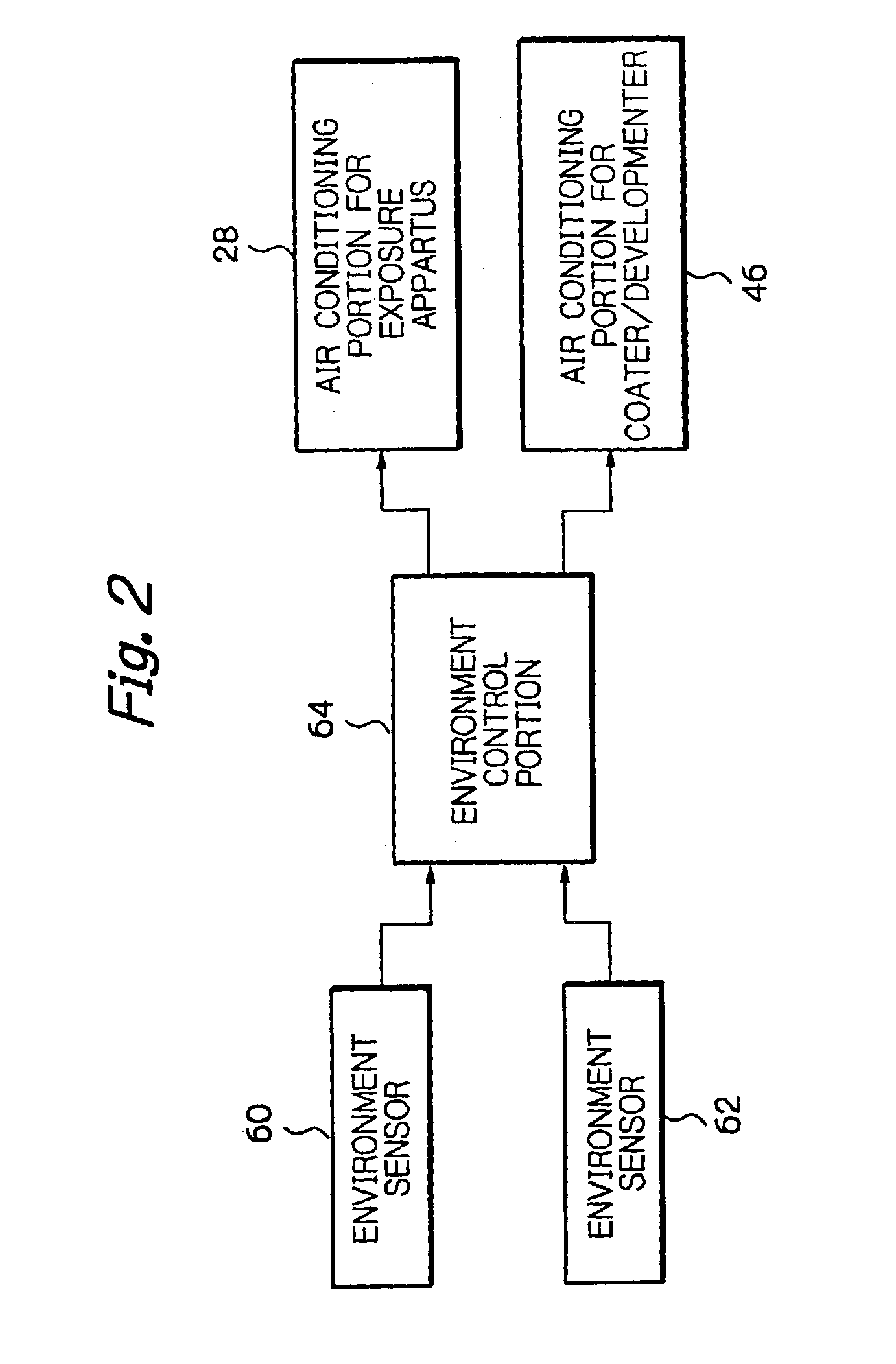
[0032]The exposure apparatus 20 includes an exposure chamber 24 for the exposure apparatus, and an exposure apparatus body 22 and a wafer loader 26 which are housed in the exposure chamber 24. An air co...


PUM

PropertyMeasurementUnit
pressureaaaaaaaaaa
temperatureaaaaaaaaaa
humidityaaaaaaaaaa

Abstract

A lithography system of in-line type includes environment sensors disposed within a chamber in which an exposure apparatus body is housed and a chamber in which a coater / developer body is housed. During a lithography process, on the basis of measured values such as air pressure temperature and humidity measured by the environment sensors, and environment control portion controls air conditioning portions in such a manner that the environmental conditions in the chambers becomes substantially the same as each other. Whereby, even when a wafer is transferred through a connecting portion, the environmental conditions in the chambers do not badly influence each other.

Description

[0001]This application is a continuation of prior application Ser. No. 09 / 350,923 filed Jul. 12, 1999, now abandoned, which is a continuation of prior application Ser. No. 09 / 055,954 filed Apr. 7, 1998, now abandoned.BACKGROUND OF THE INVENTION[0002]The present invention relates to a lithography system, and more particularly, it relates to a lithography system having an exposure apparatus for exposing a substrate to project a pattern onto it on which resist is coated, and a substrate processing apparatus connected to the exposure apparatus and adapted to process the substrate.[0003]In a lithography process mainly effected by an exposure apparatus to manufacture semi-conductor elements and the like, resist is coated on a surface of a substrate such as a wafer by a coater, and, after the substrate is transferred, by a conveying system, to the exposure apparatus, where the exposure process is effected, the exposed substrate is further developed by a developer. In this way, a resist pat...

Claims


Application Information

Patent Timeline
Patent Type & Authority Patents(United States)
IPC IPC(8): G03B27/42G03B27/52G03F7/20
CPCG03F7/70858G03F7/70991G03F7/70933
Inventor SHIRATA, YOSUKE
Owner NIKON CORP
Why Eureka
Try Eureka