Optical path changing polarizer

Inactive Publication Date: 2005-04-19
NITTO DENKO CORP
View PDF40 Cites 15 Cited by
  • Summary
  • Abstract
  • Description
  • Claims
  • Application Information

AI Technical Summary

Benefits of technology

[0013]On the other hand, according to the present invention, the optical path control type polarizer, which uses slope reflection to control the optical path of light, mainly utilizes light exhibiting a peak in a direction of regular reflection and controls the optical path of the reflected light. Hence, directivity, especially frontal directivity, favorable for display can be provided easily. Hence, a bright transmission mode can be achieved. Also in a reflection mode, flat portions of the polarizer except the optical path changing slopes can be utilized, and efficient entrance, reflection and transmission of external light can be ensured. Hence, the state of light can be balanced easily so as to be favorable to both reflection and transmission modes. Moreover, in the transmission mode, the optical path changing polarizer is bonded to a liquid-crystal cell, or the like. Hence, when the refractive index of a material for forming

Problems solved by technology

In the meanwhile, it is difficult to reduce thickness, size and weight of a transmission type liquid-crystal display device provided with a back-lighting system using a background-art bottom type or side-lighting type light pipe.
If there is no half-transmission type reflector, viewing in a reflection mode by using external light is so dark that the liquid-crystal display device substantially hardly functions as a reflection type liquid-cry

Method used


Image

  • Optical path changing polarizer
  • Optical path changing polarizer
  • Optical path changing polarizer

Examples


example 1

[0083]An acrylic ultraviolet-curable resin (ARONIX UV-3701 made by TOAGOSEI Co., Ltd.) was dropped by a dropper so that a mold processed into a predetermined shape in advance was filled with the acrylic ultraviolet-curable resin. A triacetylcellulose (TAC) film (having a saponified surface) 80 μm thick was quietly set on the acrylic ultraviolet-curable resin and then brought in close contact with the acrylic ultraviolet-curable resin by a rubber roller so that a surplus of the resin and air bubbles were removed. Then, the acrylic ultraviolet-curable resin containing the TAC film was irradiated with ultraviolet rays by a metal halide lamp so that the resin was hardened. Then, the hardened resin was stripped off from the mold and cut into a predetermined size. Thus, a transparent protective film was obtained on the TAC film having a refractive index of 1.49. The transparent protective film had an optical path changing means layer with a refractive index of 1.52.

[0084]Then, the transpa...

example 2

[0087]An optical path changing means layer was formed in the manner similar to that in Example 1 except that the TAC film was replaced by a polycarbonate (PC) film 75 μm thick. Then, the optical path changing means layer was stripped off from the PC film. Thus, an optical path changing film was obtained. TAC films 80 μm thick were bonded to both surfaces of a polyvinyl alcohol polarizing film through a polyvinyl alcohol adhesive agent to thereby form a polarizer. The optical path changing film was bonded to one surface of the polarizer through an acrylic adhesive layer having a refractive index of 1.51 so that the optical path changing means layer was positioned outside. An acrylic adhesive layer having a refractive index of 1.51 was attached to the other surface of the polarizer. The polarizer was covered with a strip sheet. Thus, an optical path changing polarizer was obtained. Then, a reflection-transmission double type liquid-crystal display device was obtained in the manner sim...

example 3

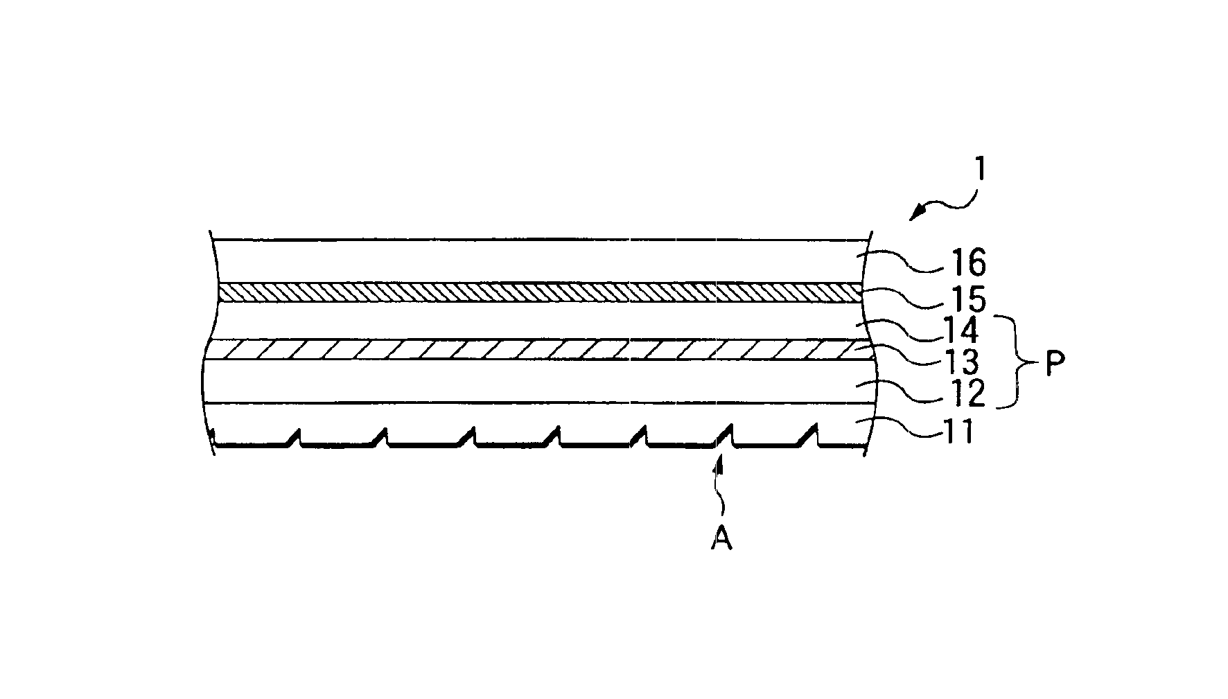
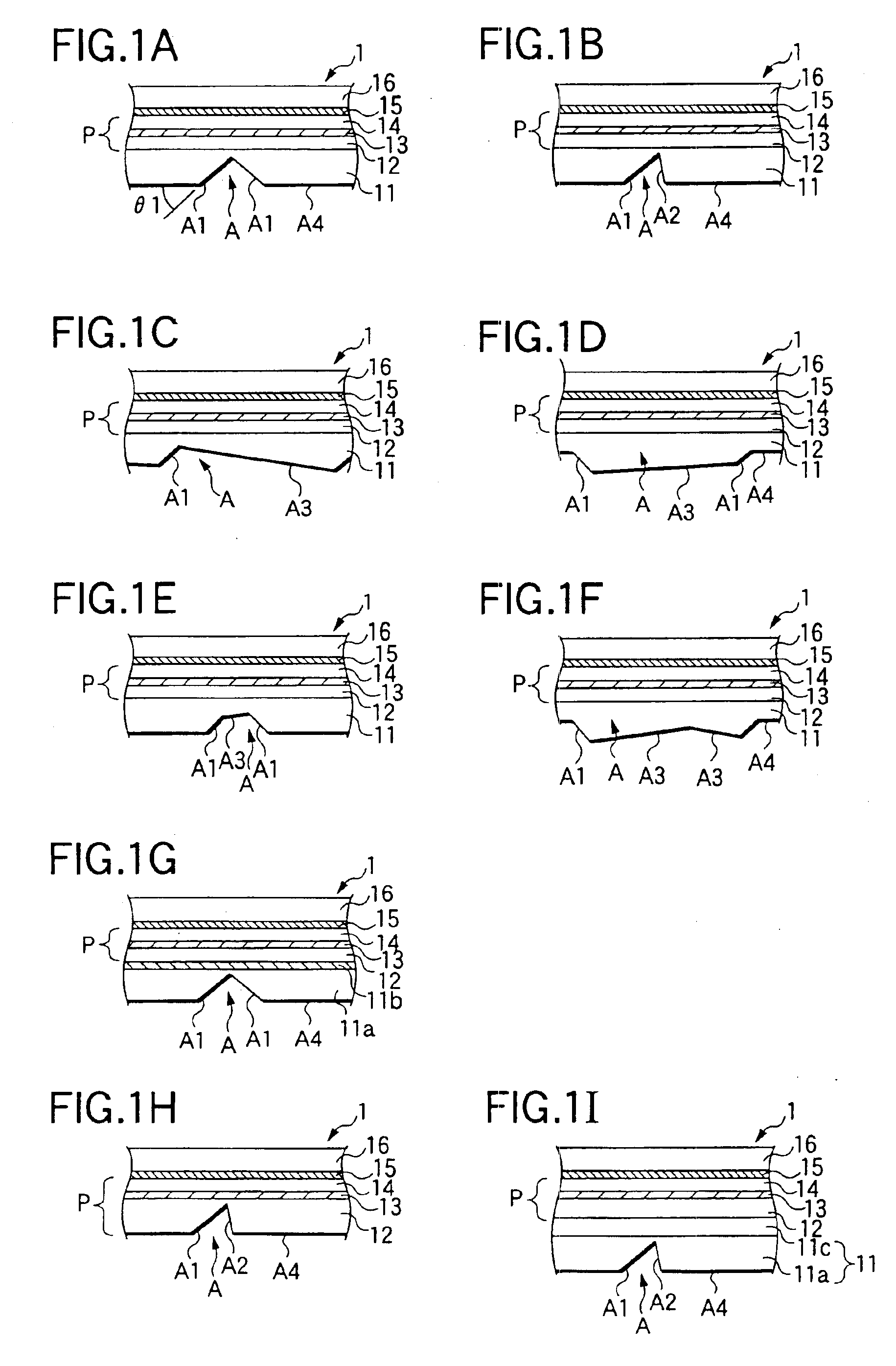
[0088]A different mold was used to obtain an optical path changing film having a plurality of optical path changing means (FIG. 1B). The plurality of optical path changing means had prism-like concave portions disposed at intervals of a pitch of 210 μm. Each of the prism-like concave portions had an optical path changing slope A1, and a steep slope A2. The inclination angle of each of the optical path changing slopes A1 was about 42 degrees. The projected width of each of the optical path changing slopes A1 on a plane of the polarizer was in a range of from 10 to 16 μm. A vertex angle between the optical path changing slope A1 and the steep slope A2 was about 70 degrees. The optical path changing means further had flat surfaces A4. The projected area of the flat surfaces A4 on the polarizer plane was not smaller than 10 times as large as the total projected area of the optical path changing slopes A1 and the steep slopes A2 on the polarizer plane. An optical path changing polarizer ...


PUM


Abstract

An optical path changing polarizer has a polarizer including a polarizing element and a transparent protective layer disposed on at least one side of the polarizing element, an adhesive layer disposed on one side surface of the polarizer, and a repetitive prismatic structure disposed on the other side of the polarizer. The repetitive prismatic structure includes optical path changing slopes aligned in a substantially constant direction so as to be inclined at an inclination angle of from 35 to 48 degrees with respect to a plane of the polarizer. Each of respective refractive indexes of the adhesive layer and a material for forming the optical path changing slopes is not lower than a refractive index of the polarizing element or the transparent protective layer. The adhesive layer has a refractive index different by 0.1 or less from a refractive index of a surface layer of the one side of the polarizer.

Description

BACKGROUND OF THE INVENTION[0001]1. Field of the Invention[0002]The present invention relates to an optical path changing polarizer by which the optical path of the light incident on one of side surfaces of a liquid-crystal display device is changed to a viewing direction efficiently, and with which it is possible to form a transmission type or reflection-transmission double type liquid-crystal display device which is small in thickness, which is light in weight, and display of which is bright and easy to view.[0003]The present application is based on Japanese Patent Applications No. 2000-4242 and 2000-167162, which are incorporated herein by reference.[0004]2. Description of the Related Art[0005]Greater reduction in thickness, size and weight of transmission type liquid-crystal display devices has been demanded for purposes of suppression of increase in weight which is accompanied by increase in size of television and personal computer display screens, reduction in size and weight ...

Claims


Application Information

Patent Timeline
IPC IPC(8): F21V8/00G02B5/30G02F1/1335G02F1/13G02B6/00
CPCG02B5/3025G02F1/133553G02B6/0056G02B6/0036G02B6/0061G02B6/0038G02F1/13363
Inventor UMEMOTO, SEIJIARIYOSHI, TOSHIHIKOSUZUKI, TAKAO
Owner NITTO DENKO CORP
Why Eureka
Try Eureka