Optical device, optical unit and projector

a technology of optical devices and projectors, applied in the field of optical devices, optical units and projectors, can solve the problems of reducing and deteriorating the liquid crystal panel and polarization plate, so as to achieve the effect of reducing the size of the projector and further enhancing the cooling efficiency of the optical devi

Inactive Publication Date: 2005-04-19
SEIKO EPSON CORP
View PDF8 Cites 76 Cited by
  • Summary
  • Abstract
  • Description
  • Claims
  • Application Information

AI Technical Summary

Benefits of technology

[0015]An object of the present invention is to provide an optical device, an optical unit and a projector capable of achieving size reduction and high luminance and capable of obtaining excellent cooling efficiency.

Problems solved by technology

However, since the size of the optical device itself is reduced in accordance with recent size reduction and increase in luminance of projector, which results in small gap between the liquid crystal panel and the polarization plate, it is difficult for the cooling air to enter into the gap, thereby lowering cooling efficiency and deteriorating liquid crystal panel and polarization plate.
The cooling efficiency can be improved by increasing the amount of the cooling air flowing through the gap, which, however, increases the noise of the cooling fan.
Further, in order to increase the amount of the cooling air, the size of the cooling fan has to be increased, which requires greater size of the projector itself to hinder size reduction of the projector.
However, according to the optical device where the heat is transferred to the base, the heat generated on the polarization plate and the liquid crystal panel may not be entirely transferred to the base and the heat may conduct from high-temperature polarization plate to relatively low-temperature liquid crystal panel according to the polarization plate and the liquid crystal panel, so that the temperature of all the polarization plate and the liquid crystal panel may not be securely cooled and sufficient cooling efficiency may not be obtained.
Further, since sufficient cooling efficiency cannot be obtained, size reduction and enhancement in luminance of the projector may be hindered.

Method used


Image

  • Optical device, optical unit and projector
  • Optical device, optical unit and projector
  • Optical device, optical unit and projector

Examples


first embodiment

[First Embodiment]

[0089]A projector according to a first embodiment of the present invention will be described below with reference to attached drawings.

[1-1 Primary Arrangement of Projector]

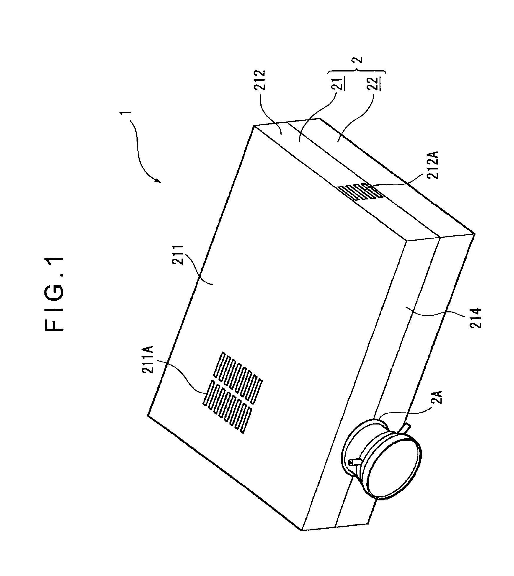
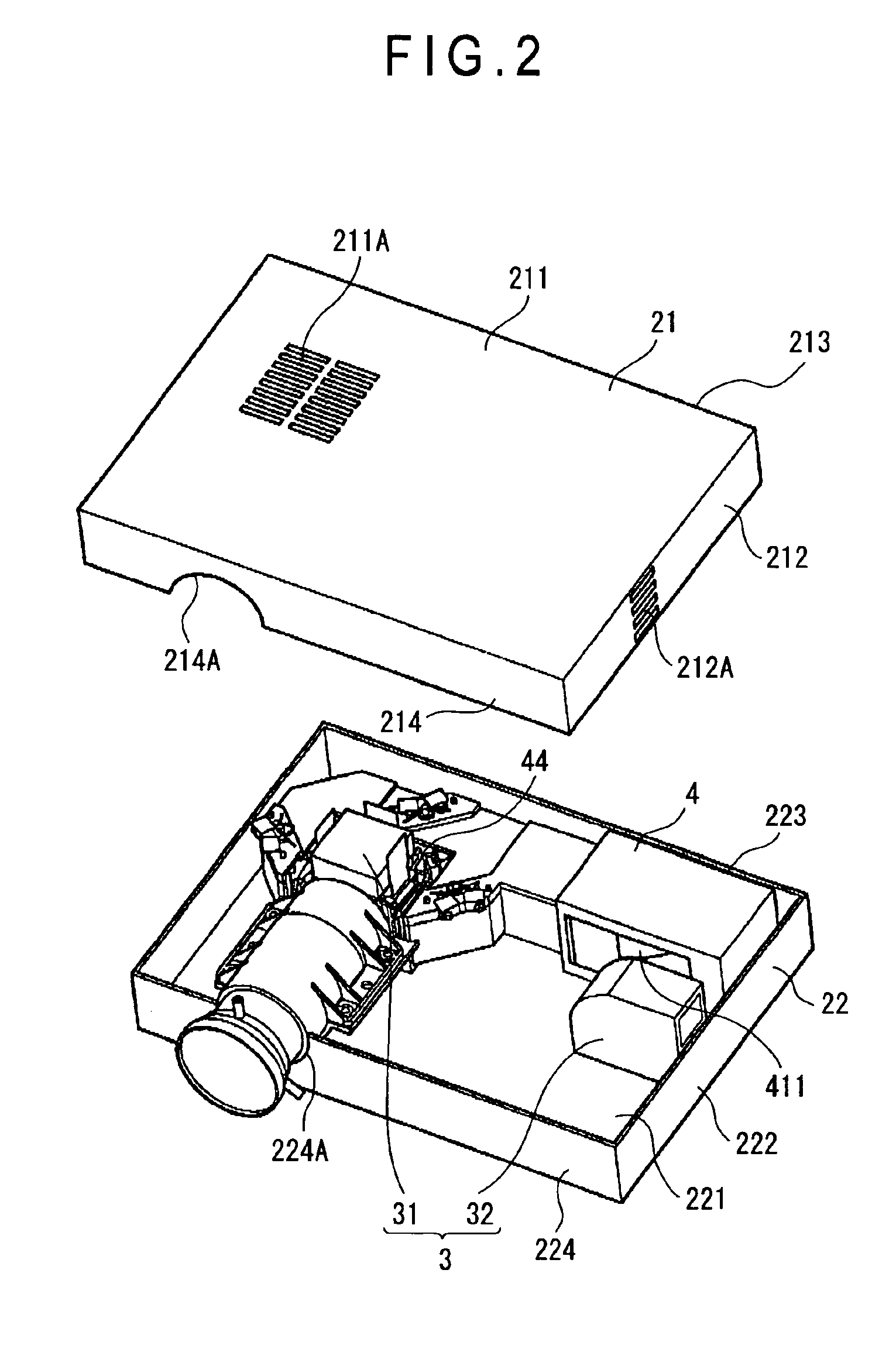
[0090]FIG. 1 is an entire perspective view seen from above showing a projector 1 according to first embodiment of the present invention, and FIG. 2 is an exploded perspective view with an upper case 21 being detached from FIG. 1.

[0091]The projector 1 has an approximate rectangular parallelepiped exterior case 2, a cooling unit 3 for cooling the heat in the projector 1, and an optical unit 4 for optically processing a light beam irradiated by a light source to form an optical image corresponding to image information.

[0092]Incidentally, though not specifically shown in FIG. 2, a power source block and a lamp driving circuit etc. are accommodated in the space in the exterior case 2 except for the optical unit 4.

[0093]The exterior case 2 has an upper case constituting the top side, front side and la...

second embodiment

[2, Second Embodiment]

[0227]A projector according to a second embodiment of the present invention will be described below.

[0228]The projector according to the second embodiment differs to the projector 1 of the first embodiment only in the arrangement for connecting the heat-conductive plate 447 fixed to the holding frame 447 accommodating the liquid crystal panels 441R, 441G and 441B with the heat-conductive frames 484 and 485 attached to the lower light guide 48. Accordingly, the same reference numerals will be attached to the components identical with or corresponding to those of the first embodiment to omit or simplify the description thereof.

[2-1. Structure of Optical Device]

[0229]FIGS. 15 to 17 are cross sections showing primary portions of the optical device 44 and the heat-conductive frame 484, which respectively show different arrangements for connecting the heat-conductive plate 447 and the heat-conductive frame 484.

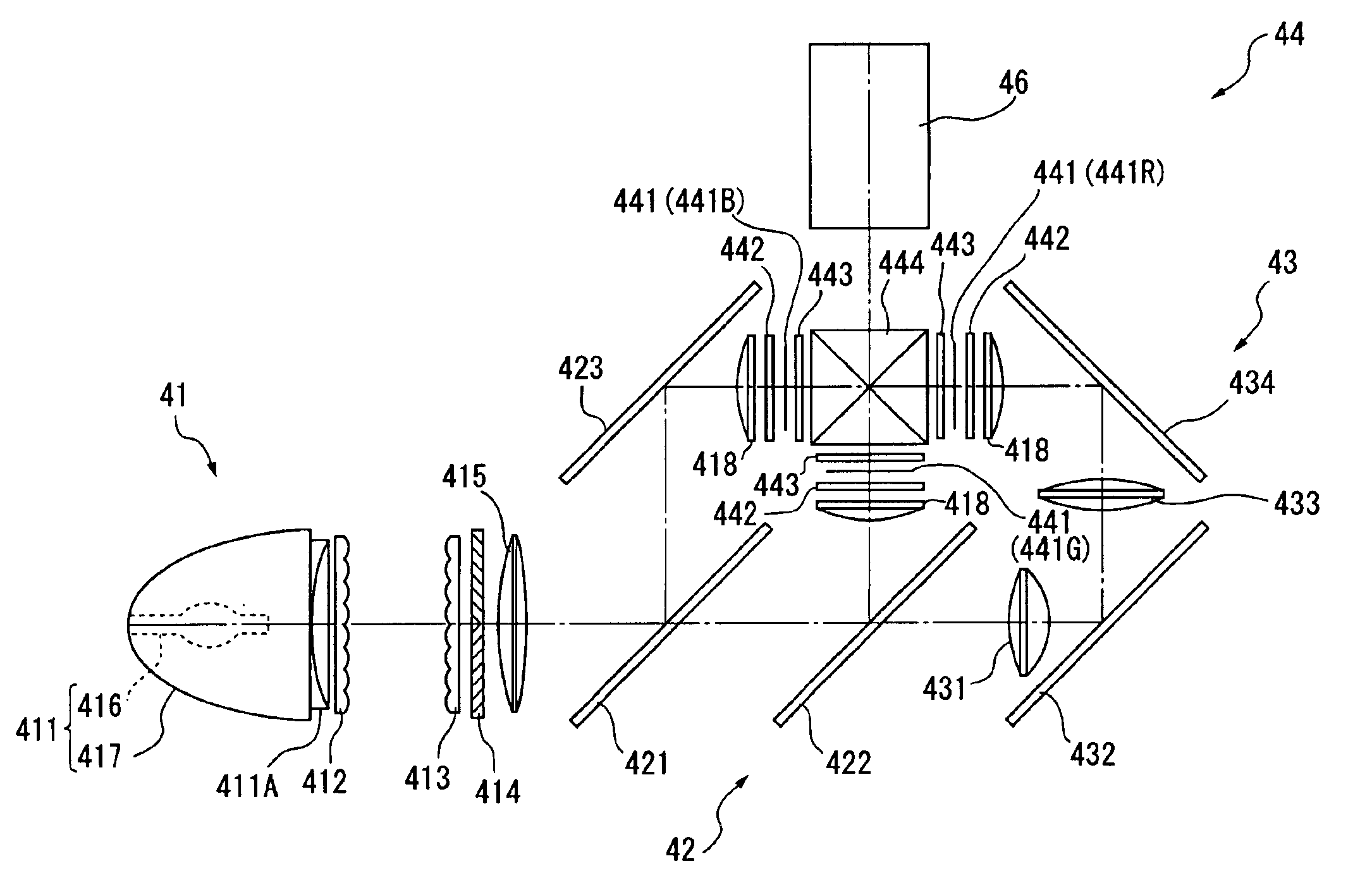
[0230]As shown in FIGS. 15 to 17, the optical device 44 h...

third embodiment

[3. Third Embodiment]

[0242]A projector according to third embodiment of the present invention will be described below.

[0243]The projector according to the third embodiment of the present embodiment differs to the projector 1 of the first and the second embodiments only in the bonding arrangement for accommodating and fixing the liquid crystal panels 441R, 441G and 441B of the optical modulator 440 to the holding frame 446. Accordingly, the same reference numeral will be attached to the components identical with or corresponding to those of the first and the second components to omit or simplify the description thereof.

[3-1. Structure of Optical Modulator]

[0244]FIG. 18 is an exploded perspective view of the optical modulator 440.

[0245]As shown in FIG. 18, the optical modulator 440 has the liquid crystal panel 441 identical with that of the first embodiment including the drive substrate 441D and the opposing substrate 441E, the irradiation-side dustproof plate 441S and the incident-si...


PUM


Abstract

An optical device (44) is provided with an optical modulator (440), a color combining optical device (444) and an optical converting element (443), the optical modulator (440) being attached to the color combining optical device (444) through a position-adjusting spacer (449) made of a heat-insulative material, so that heat generated on the optical modulator (440) and the optical converting element (443) is mutually insulated by the spacer (449) made of heat-insulative material and does not conduct from high-temperature side to low-temperature side between the optical modulator (440) and the optical converting element (443), thus improving cooling efficiency of the optical modulator (440) to enable size reduction and high luminance of the optical device (44) and a projector.

Description

BACKGROUND OF THE INVENTION[0001]1. Field of the Invention[0002]The present invention relates to an optical device integrating an optical modulator for modulating color light in accordance with image information and a color combining optical device for combining the color light modulated by the optical modulator, an optical unit provided with the optical device and a projector provided with the optical unit.[0003]2. Description of Related Art[0004]Conventionally, so-called three-plate projector in which a light beam irradiated by a light source is separated into three color-lights of red, green and blue which are modulated by three liquid crystal panels for respective color-lights in accordance with image information and are combined by a cross dichroic prism after being modulated, and a color image is enlarged and projected through a projection lens, is known.[0005]Since the respective liquid crystal panels of such projector have to be located at back-focus position of the projecti...

Claims


Application Information

Patent Timeline
Patent Type & Authority Patents(United States)
IPC IPC(8): H04N9/31G02F1/13G03B21/00G03B21/16H05K7/20
CPCH04N9/3105H04N9/3141H04N9/3197H04N9/3167H04N9/3144G03B21/145G03B21/16
Inventor YANAGISAWA, YOSHIYUKI
Owner SEIKO EPSON CORP
Why Eureka
Try Eureka