Flat aluminum electrolytic capacitor and method of manufacturing the same

a technology of aluminum electrolytic capacitor and aluminum electrolytic capacitor, which is applied in the direction of feed-through capacitors, electrical apparatus casings/cabinets/drawers, casings/cabinets/drawers details, etc., can solve the problems of occupying too much space on the circuit board compared to other electronic components, and reducing the thickness of the apparatus, so as to reduce the void in the casing

Inactive Publication Date: 2005-04-19
RUBYCON CORPORATION
View PDF8 Cites 49 Cited by
  • Summary
  • Abstract
  • Description
  • Claims
  • Application Information

AI Technical Summary

Benefits of technology

[0021]The eighth aspect of the present invention is the method of manufacturing a flat aluminum electrolytic capacitor according to any one of the first to third aspects of the invention, wherein the flexible casing is sealed under the condition of reduced pressure of below 1 atm. in order to reduce voids in the casing, after encasing the capacitor element in the flexible casing.
[0023]The tenth aspect of the present invention is the method of manufacturing a flat aluminum electrolytic capacitor according to any one of the first to third aspects of the invention, wherein the aging treatment is carried out under reduced pressure.

Problems solved by technology

As electronic apparatuses and optical apparatuses such as cameras have become smaller in profile and in thickness, the conventional aluminum electrolytic capacitor of cylindrical configuration is viewed as too large and it takes too much space on a circuit board compared to other electronic components.
Although capacitors may be made flat instead of the cylindrical construction, there is a dimensional limitation in manufacturing the flat capacitor thus generating an obstacle to making apparatuses smaller in profile and in thickness.
Hydrogen gas generated rapidly during the aging treatment cannot be discharged with this construction.
Even during normal operation, the gas pressure rises so as to cause deformation of the capacitor and / or degradation of performance at times when hydrogen gas is generated at a high rate which cannot be accommodated by the rubber sealant.
As a result, it has been common to use a metal casing that is strong but is not easy to process into a desired shape, in order to ensure performance and strength.
However, as such a casing has insufficient strength, troubles such as swelling or rupture of the capacitor, deformation of the capacitor element and degradation of the characteristics of the capacitor, occur when the inside pressure of the casing rises as hydrogen gas is generated during the aging treatment.
In the case of aluminum electrolytic capacitor of flat configuration or stacked structure, the foil electrode is more liable to stress and damage the dielectric film compared to the conventional aluminum electrolytic capacitor of cylindrical shape.
As a consequence, there have been such problems as a significant amount of hydrogen gas is generated during the aging treatment, thereby causing the casing to swell, deform or rupture, the electrolytic solution to leak, the capacitor element to be deformed by the hydrogen gas, and the characteristics of the capacitor to deteriorate.

Method used


Image

  • Flat aluminum electrolytic capacitor and method of manufacturing the same
  • Flat aluminum electrolytic capacitor and method of manufacturing the same
  • Flat aluminum electrolytic capacitor and method of manufacturing the same

Examples


example 1

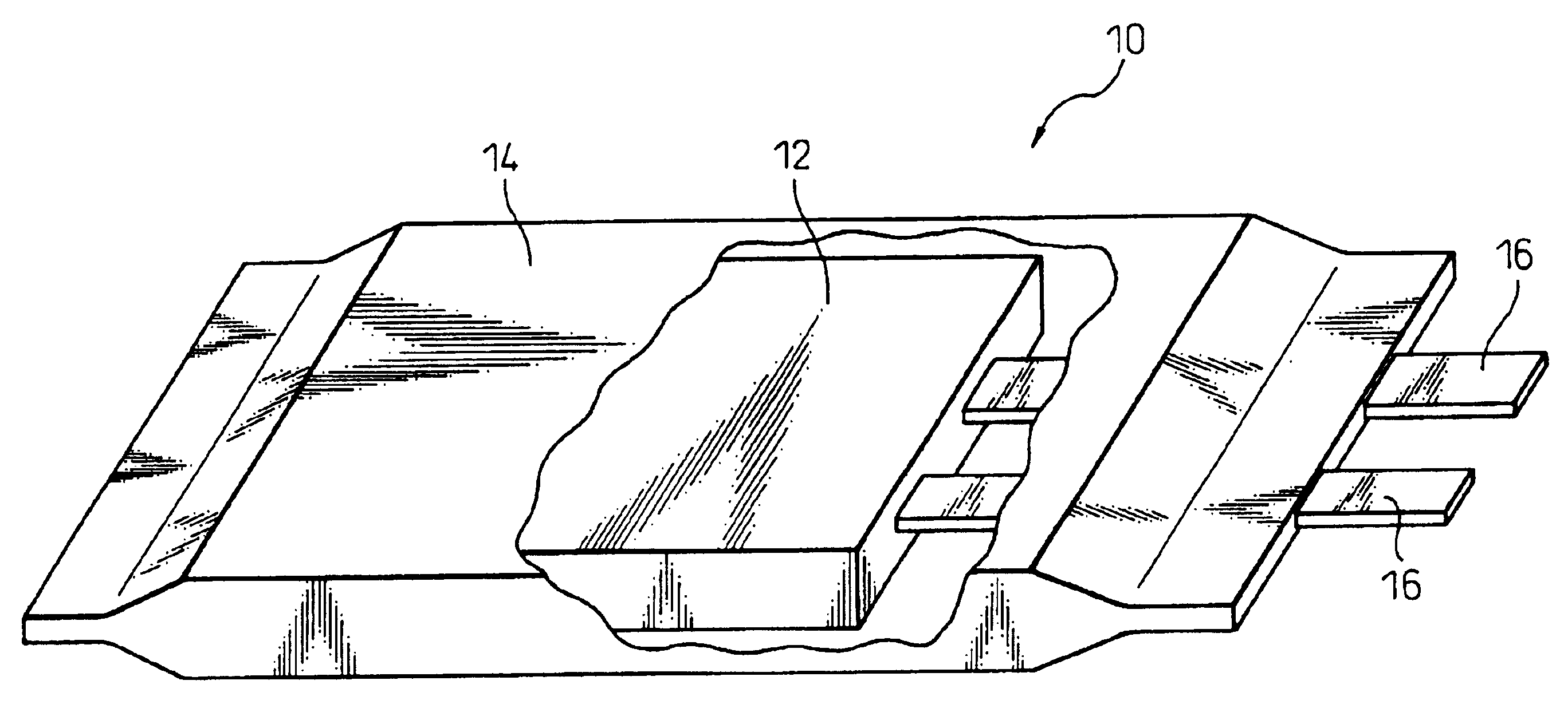
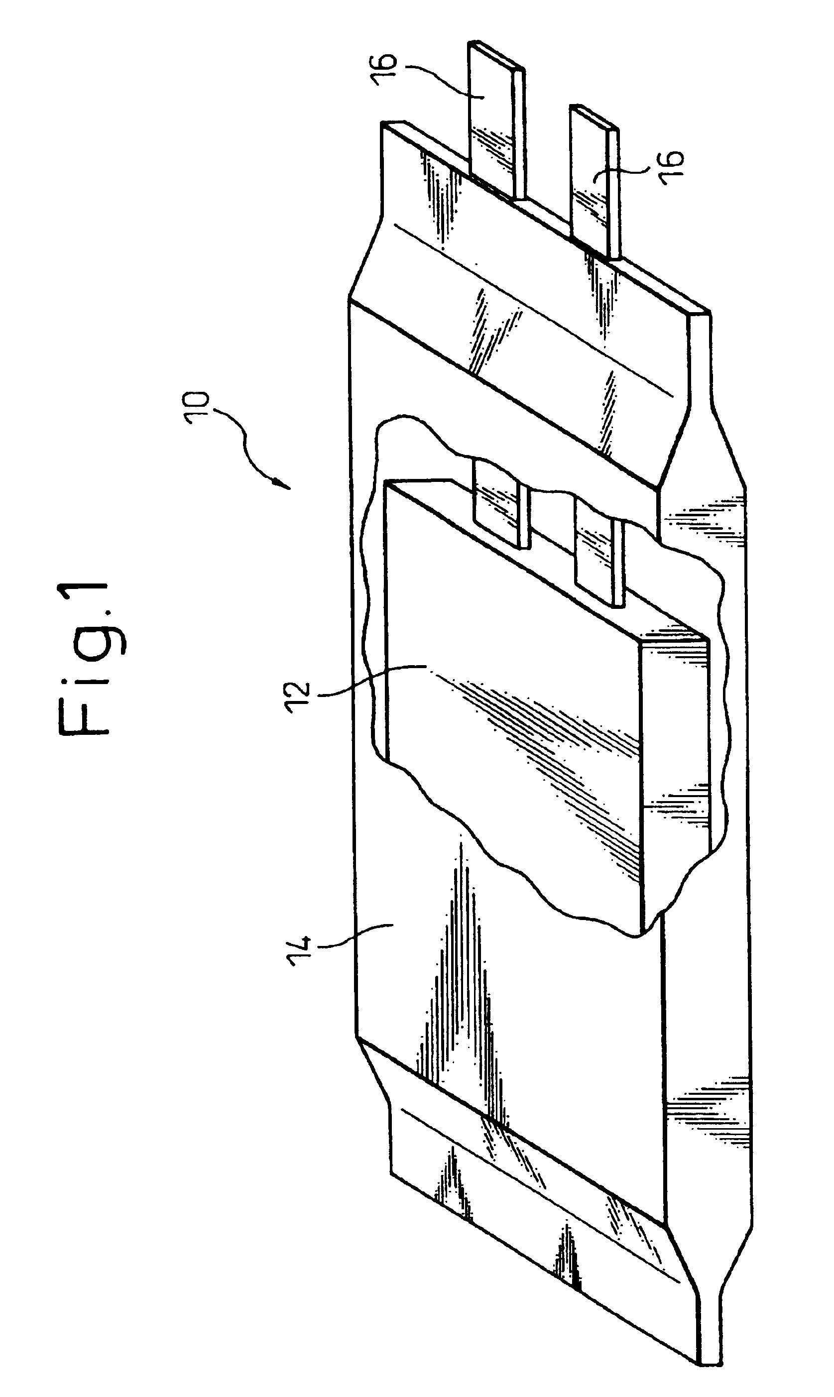
[0094]The capacitor element impregnated with the electrolytic solution was encased in a flexible casing made of PET, aluminum and acid-denatured PP and, after being subjected to an aging treatment with 330 V applied at ambient temperature of 75° C. for one hour, the flexible casing was hermetically sealed thereby to make a capacitor element. Then the flat aluminum electrolytic capacitor having the outer casing was made by the method described above.

example 2

[0095]The capacitor element being impregnated with the electrolytic solution was subjected to an aging treatment with 330 V applied at ambient temperature of 20° C. for one hour, and was encased in a flexible casing made of PP that was then hermetically sealed thereby to make a capacitor element. Then the flat aluminum electrolytic capacitor having the outer casing was made by the method described above.

example 3

[0096]The capacitor element impregnated with the electrolytic solution was, after applying voltage of up to 350 V at ambient temperature of 20° C., subjected to an aging treatment with 330 V applied at ambient temperature of 85° C. for one hour followed by another aging treatment with 350 V applied at ambient temperature of 20° C., with the capacitor element being encased in the flexible casing made of PP that was hermetically sealed under reduced pressure of 100 mmHg thereby to make a capacitor element. Then the flat aluminum electrolytic capacitor having the outer casing was made by the method described above.


PUM

PropertyMeasurementUnit
pressureaaaaaaaaaa
pressureaaaaaaaaaa
pressureaaaaaaaaaa

Abstract

The present invention relates to a method of manufacturing a flat aluminum electrolytic capacitor comprising a separator impregnated with an electrolytic solution, an anode foil and a cathode foil, a flat capacitor element that has external lead-out terminals connected respectively to the anode foil and the cathode foil, and a flexible casing that houses the capacitor element and is hermetically sealed, said method comprising the steps of encasing the capacitor element in the flexible casing and applying aging treatment before hermetically sealing the casing, and hermetically sealing the flexible casing, and also relates to a flat aluminum electrolytic capacitor comprising a separator impregnated with the electrolytic solution, the anode foil and the cathode foil, the flat capacitor element that has the external lead-out terminals connected respectively to the anode foil and the cathode foil, and the flexible casing that houses the capacitor element and is hermetically sealed, wherein the electrolytic capacitor is subjected to an aging treatment before the capacitor element is encased in the flexible casing which is hermetically sealed.

Description

BACKGROUND OF THE INVENTION[0001]1. Field of the Invention[0002]The present invention relates to a flat aluminum electrolytic capacitor and a method of manufacturing the same. More particularly, the present invention relates to a flat aluminum electrolytic capacitor, comprising a capacitor element having a stacked structure or a capacitor element having wound structure, that is encased in a hermetically sealed flexible casing, and a method of manufacturing the same.[0003]2. Description of the Related Art[0004]Electrolytic capacitors have conventionally been manufactured by encasing a capacitor element, comprising two electrode foils (an anode foil and a cathode foil) and a separator interposed therebetween which are wound in a roll, in a cylindrical metal casing, and stopping the openings of the metal casing with a terminal board having lead terminals.[0005]As electronic apparatuses and optical apparatuses such as cameras have become smaller in profile and in thickness, the conventi...

Claims


Application Information

Patent Timeline
Patent Type & Authority Patents(United States)
IPC IPC(8): H01G9/10H01G9/035H01G9/00H01G9/04H01G9/08
CPCH01G9/10Y10T29/417
Inventor UZAWA, SHIGERUMAKINO, YOSHIKIKAMAKURA, KATSUHISAKOBAYASHI, YUUICHIKOMATSU, AKIHIKOMATSUZAWA, TAKETO
Owner RUBYCON CORPORATION
Why Eureka
Try Eureka