Electronic apparatus

Inactive Publication Date: 2005-04-19
SONY CORP
View PDF4 Cites 58 Cited by
  • Summary
  • Abstract
  • Description
  • Claims
  • Application Information

AI Technical Summary

Benefits of technology

[0027]The present invention has been made in view of the above, and it is accordingly an object of the present invention to provide an electronic apparatus that can reduce power consu

Problems solved by technology

Therefore, even when the operating state of the satellite broadcasting receiver 10 is changed from a normal state for performing normal operation to a standby state for reducing power consumption by stopping the normal operation, these circuits consume power.
Therefo

Method used


Image

  • Electronic apparatus
  • Electronic apparatus
  • Electronic apparatus

Examples


first embodiment

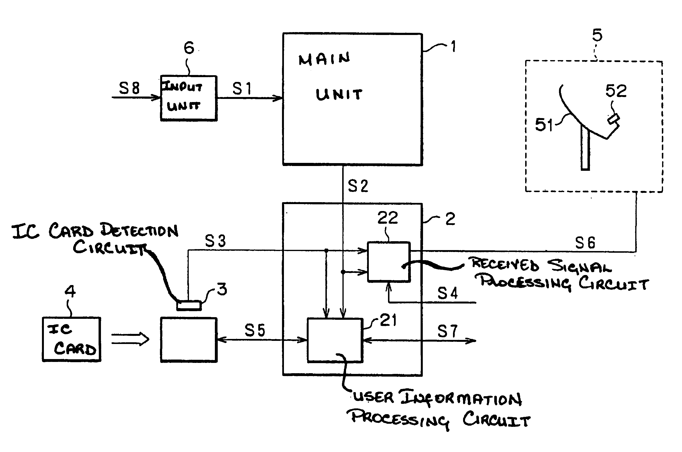
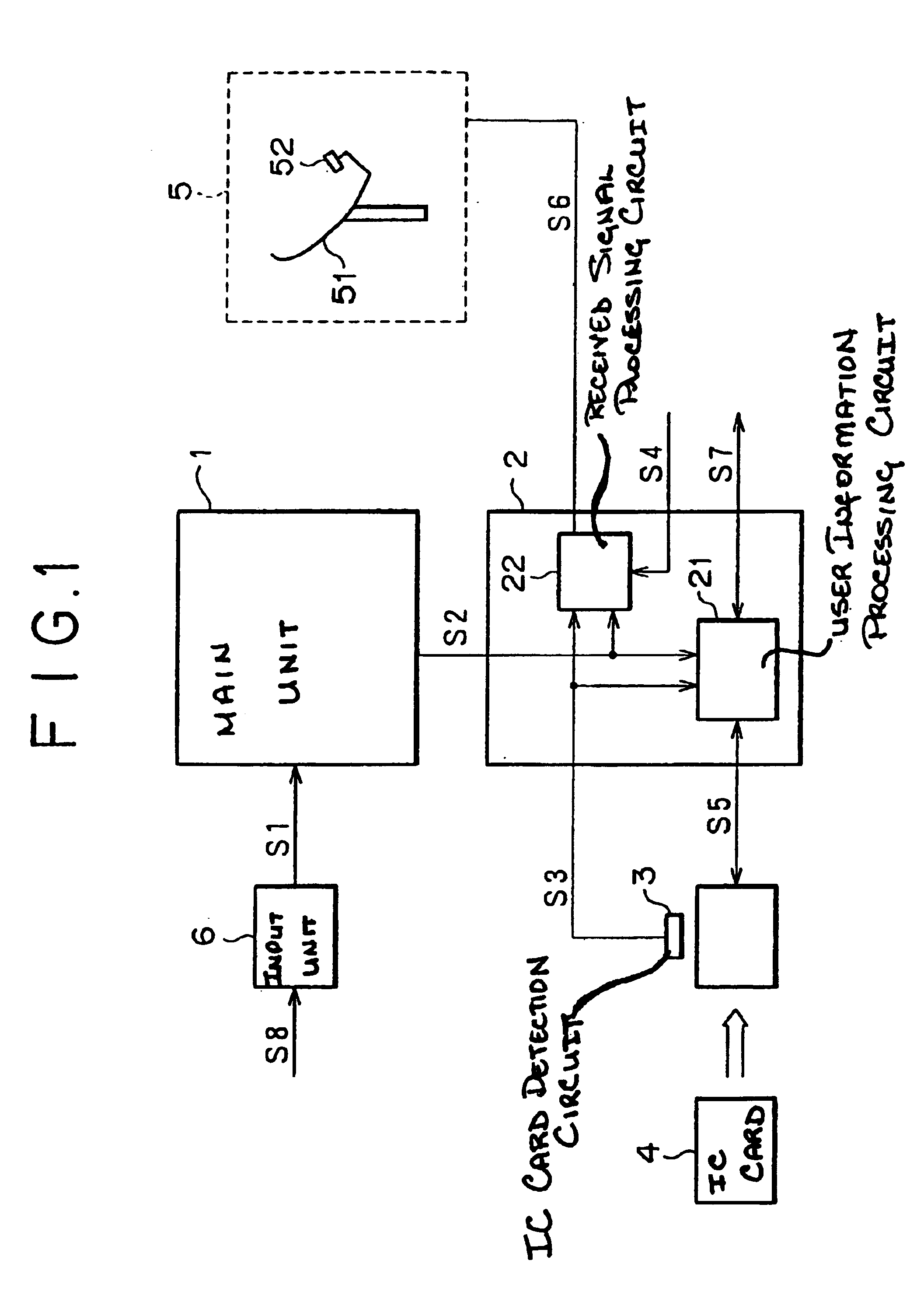
[0037]Preferred embodiments of an electronic apparatus according to the present invention will hereinafter be described with reference to the drawings. FIG. 1 shows an electronic apparatus including a satellite broadcasting receiver according to the present invention. The same reference numerals in FIG. 1 and FIG. 4 denote the same. Reference numeral 1 denotes a main unit of the electronic apparatus; reference numeral 2 denotes a sub-unit of the electronic apparatus; reference numeral 21 denotes a user information processing circuit; reference numeral 22 indicates a received signal processing circuit; reference numeral 3 indicates an IC card detection circuit; reference numeral 6 indicates an input unit of the electronic apparatus; S1 designates an apparatus control signal; S2 designates a state signal; S3 designates an IC card detection signal; S4 denotes a feed selection signal; and S5 denotes an IC card record signal.

[0038]The input unit 6 receives and processes an apparatus oper...

second embodiment

[0072]an electronic apparatus according to the present invention will next be described.

[0073]FIG. 3 shows a second embodiment of an electronic apparatus including a satellite broadcasting receiver according to the present invention. The same reference numerals in FIG. 1 and FIG. 3 denote the same. Reference numerals 11 to 13 each denote a satellite broadcasting receiver; reference numerals S61 to S64 each denote a feed line to an antenna device 5; reference numeral 6 denotes a feed line distributor.

[0074]The feed lines S61 to S63 for supplying voltage from the satellite broadcasting receivers 11 to 13 to the antenna device 5, respectively, are connected to the distributor 15 at an intermediate point to be thus integrated into a single feed line S64. The feed line S64 is connected between the distributor 15 and the antenna device 5.

[0075]In FIG. 3, the feed line S61 represented by a solid line denotes a feed line that is supplying voltage to the antenna device 5, while the feed line...


PUM


Abstract

An electronic apparatus according to the present invention comprises a main unit which stops operation when receiving an apparatus control signal S1 specifying a standby state while in a normal state, and then outputs an operating state signal S2 indicating that the main unit is in the standby state; and begins operation when receiving an apparatus control signal S1 for selecting the normal state while in the standby state, and then outputs an operating state signal S2 indicating that the main unit is in the normal state; and a sub-unit which stops operation when, while operating, receiving an IC card detection signal S3 indicating that the reading of an IC card 4 is possible and also receiving the operating state signal S2 indicating that the main unit is in the standby state from the main unit, and brings part of its functional blocks into operation when, while not operating, receiving the operating state signal S2 indicating that the main unit is in the normal state from the main unit.

Description

BACKGROUND OF THE INVENTION[0001]The present invention relates to an electronic apparatus having a standby state and a normal state, and particularly to an electronic apparatus that can reduce power consumption in the standby state.[0002]FIG. 4 is a diagram of assistance in illustrating operation of a conventional subscription satellite broadcasting receiver.[0003]Reference numeral 10 denotes a satellite broadcasting receiver; reference numeral 20 denotes a broadcasting station; reference numeral 30 denotes a satellite; reference numeral 4 designates an IC card; reference numeral 5 designates an antenna device; reference numeral 51 indicates a receiving antenna; reference numeral 52 indicates a low-noise frequency converter circuit; reference numeral S6 denotes a feed line; reference numeral S7 denotes a program purchase signal; reference numeral S8 indicates an apparatus operation signal; and reference numerals S11 and S12 each indicate a radio wave signal.[0004]The apparatus opera...

Claims


Application Information

Patent Timeline
IPC IPC(8): H04H1/00H04B1/38H04B1/16H04H40/90H04N5/44H04N5/63H04N7/16H04N7/20H04N21/442H04N21/443
CPCH04B1/1615H04B1/3816H04W52/0241H04H40/90Y02B60/50Y02D30/70H04N5/44
Inventor YAMAGUCHI, KAZUHIROTAKESHIMA, KURIKO
Owner SONY CORP
Why Eureka
Try Eureka