Fuel injection system

a fuel injection system and fuel injection technology, applied in liquid fuel feeders, machines/engines, mechanical equipment, etc., can solve the problems of only being optimized for a specific speed range, unable to achieve the required vortex formation, and unable to optimize turbulence-producing measures,

Inactive Publication Date: 2005-04-26
ROBERT BOSCH GMBH
View PDF14 Cites 28 Cited by
  • Summary
  • Abstract
  • Description
  • Claims
  • Application Information

AI Technical Summary

Benefits of technology

[0022]This specific embodiment allows an advantageous mixture formation, especially when no piston recess is provided, or only a very shallow one.

Problems solved by technology

Especially in partial load operation and during idling, this has a considerable effect on fuel consumption since the entire combustion chamber volume is not filled with an enriched, ignitable mixture.
Disadvantageous in this related art is that the turbulence-producing measures, such as special designs of the combustion-chamber geometry, especially the piston form designs, can only be optimized for a specific speed range.
Especially in the area of partial load and idling, i.e. when small fuel-injection quantities and low filling degrees and / or low speed are involved; the required vortex formations can only be achieved by throttling.
This, however, results in higher fuel consumption.
Moreover, it is disadvantageous that the wall-directed fuel-injection system requires a more costly piston design with a deflection edge.
In air-directed fuel-injection systems as well, the mixture conveyance to the spark plug is less than successful in idling operation and in lower partial-load operation, due to the aforementioned reasons; in mean partial-load operation it is partly only possible with unjustifiably low production variances of the high-pressure fuel injectors utilized and / or the flow guidance through the intake manifold.
The faulty reproducibility primarily manifests itself in increased emissions of unburned hydrocarbons as a result of individual combustion misses.
Disadvantageous in jet-directed fuel-injection systems is that currently used cylinder heads having a spark plug centrally positioned in the cylinder axis in the cylinder head, can only be used when substantially modified, since the additional installation space for the fuel injector in the vicinity of the spark plug requires a disadvantageous moving of the, in most cases, two intake valves.
While the currently used production tools and cylinder-head designs may in fact be compatible when the fuel injector is positioned in the cylinder wall on the side of the intake valves, the afore-described disadvantages of the air-directed and the wall-directed fuel-injection systems still occur.

Method used


Image

  • Fuel injection system
  • Fuel injection system
  • Fuel injection system

Examples


Embodiment Construction

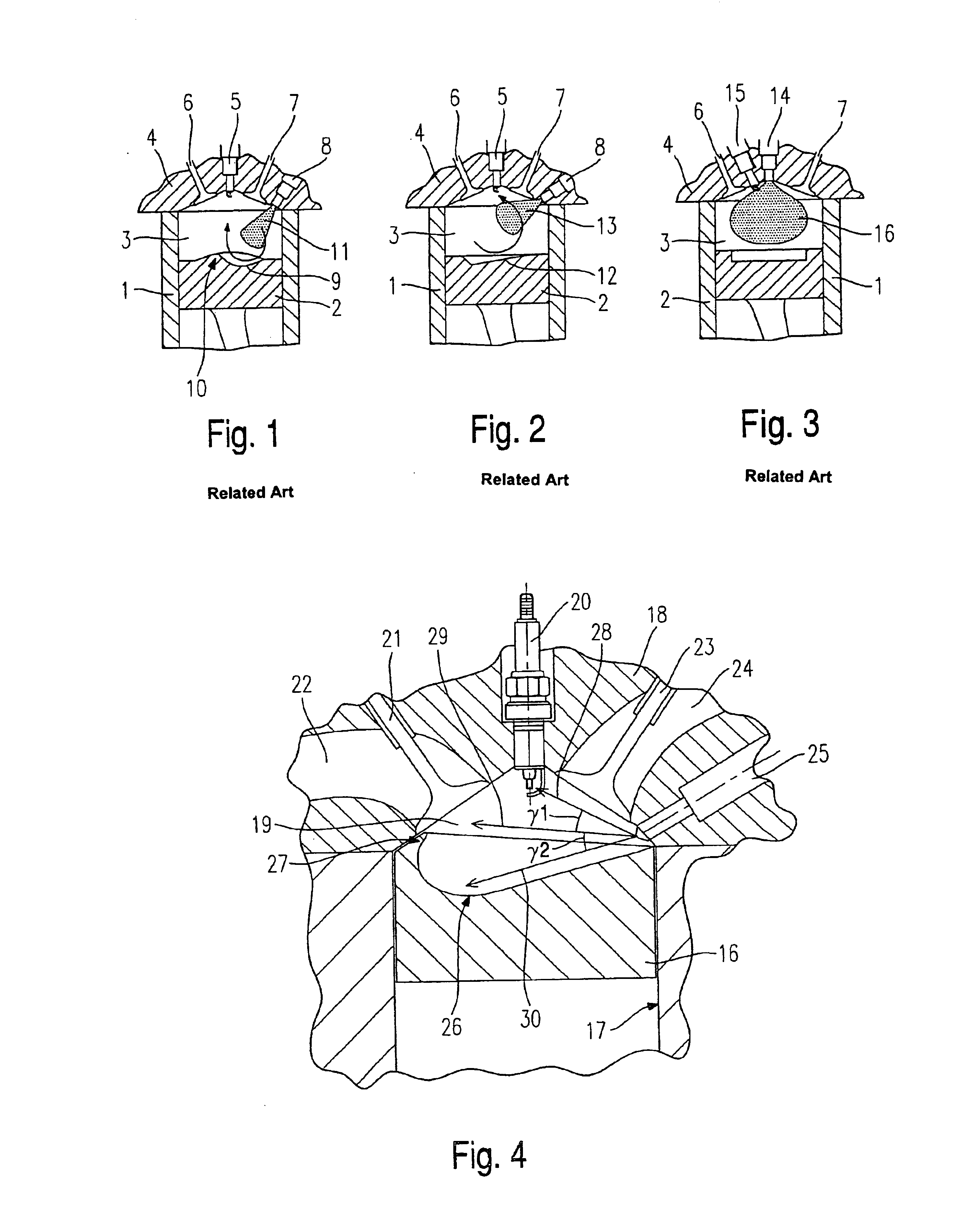
[0031]FIGS. 1, 2 and 3 schematically show the basic design of the three most important fuel-injection systems according to the related art, to first delineate the respective advantages and disadvantages and to explain to what extent the present invention combines the advantages of the fuel-injection systems while avoiding the disadvantages.

[0032]FIG. 1 shows a schematic section through a fuel-injection system according to the related art for a wall-directed combustion method. A piston 2 is guided in a cylinder 1, represented schematically in a cut-away view. A combustion chamber 3 is delimited by a cylinder head 4 resting on cylinder 1. A spark plug 5 is in the center of cylinder 1, and a discharge valve 6 and an intake valve 7 are located on the side, for the gas exchange. Normally, two intake valves 7 and discharge valves 6 are provided in most cases. A fuel injector 8 is located in cylinder head 4 on the side of intake valve 7 toward the wall of cylinder 1. Piston 2 has a distinc...


PUM


Abstract

A fuel-injection system for internal combustion engines has at least one fuel injector injecting fuel into a combustion chamber, which is delimited by a cylinder wall in which a piston is guided. A spark plug projects into the combustion chamber, and the fuel injector is located in the combustion chamber in the region of a gas-intake valve toward the cylinder wall. The fuel injector produces a plurality of fuel jets at least one of these fuel jets being tangentially oriented to the region of the spark plug.

Description

FIELD OF THE INVENTION[0001]The present invention is directed to a fuel injection system.BACKGROUND INFORMATION[0002]In mixture-compressing internal combustion engines having external ignition and internal mixture formation, stratified charge operation requires a “mixture cloud” in the region of the spark plug, which must have a particular fuel-air ratio in the ignitable range. Especially in partial load operation and during idling, this has a considerable effect on fuel consumption since the entire combustion chamber volume is not filled with an enriched, ignitable mixture.[0003]Basically, three methods are known for producing such a mixture cloud: the wall-directed, the air-directed and the jet-directed fuel-injection system.[0004]In the wall-directed fuel-injection system, the fuel is carried along by an air vortex which lies up against the wall of the cylinder and in most cases is deflected at the specially designed piston. For this purpose, a fuel injector, which is positioned ...

Claims


Application Information

Patent Timeline
Patent Type & Authority Patents(United States)
IPC IPC(8): F02M61/18F02M61/00F02B23/10F02M69/04F02B75/12F02F1/24F02B17/00F02B75/00F02F3/26F02M61/14
CPCF02B23/104F02B23/105F02M61/182F02M61/184F02M69/045F02B17/005F02B2023/103F02B2075/125Y02T10/123F02F2001/245Y02T10/125F02F3/26Y02T10/12F02B23/10
Inventor ARNDT, STEFANWURFEL, GERNOTRAIMANN, JURGENGRZESZIK, ROMAN
Owner ROBERT BOSCH GMBH
Why Eureka
Try Eureka