
Method for controlling the primary ignition current of an internal combustion engine with controlled ignition

a technology of internal combustion engine and primary ignition current, which is applied in the direction of machines/engines, mechanical equipment, instruments, etc., can solve the problems of insufficient energy delivered to the spark plug to ignite the fuel/oxidant mixture, and is fairly difficult to implemen

Active Publication Date: 2005-04-26
SIEMENS VDO AUTOMOTIVE CORP
View PDF8 Cites 5 Cited by
  • Summary
  • Abstract
  • Description
  • Claims
  • Application Information

AI Technical Summary

Benefits of technology

[0010]It is therefore an object of the present invention to provide a method for controlling the current in the primary circuit which is at least equally reliable but without requiring calibration to be carried out as is the case for the method described in the aforementioned document. Preferably, implementation of the method according to the invention does not require extra expenditure on the ignition circuit.
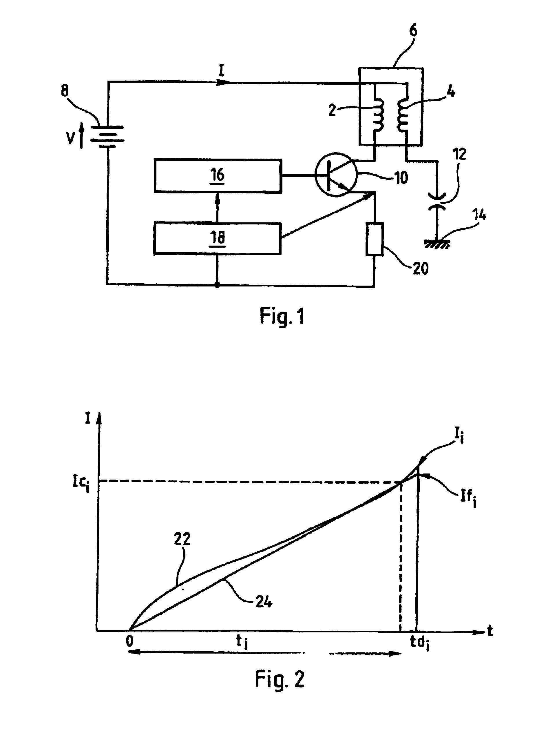
[0017]Carrying out a measurement in the last tenth of the conduction time makes it possible to obtain a good approximation of the current when the circuit is opened. This makes it possible to gain precision in the determination of the conduction time. It is thus superfluous to precisely characterize the ignition coils in order to extrapolate their behavior just before the primary circuit is opened, because the measurement which is taken gives a fairly precise indication of this behavior.
[0020]In a preferred embodiment, the estimation of the current at the end of the predetermined conduction time is carried out on the basis of a measurement by linear extrapolation. Such an extrapolation is easy to carry out, and gives very good results in the present case. A higher-order extrapolation may nevertheless be employed so as to increase the precision of the method, although the gain in precision is not very substantial in this case.
[0023]The control method according to the invention makes it possible for the desired final current to be determined as a function of the speed of the engine in question. In this case, when it is calculated on the basis of tables, the predetermined conduction time also depends on the speed of the engine in question.

Problems solved by technology

This is because the energy delivered to the spark plug will not be sufficient to ignite the fuel / oxidant mixture if this current is too weak.
However, thermal problems occur in the coil if this current is too large: it will become heated by the Joule effect if the current flowing through it is too large, which creates parasitic phenomena.
This method gives good results, but it is fairly difficult to implement because, for each type of coil, it is necessary to determine a set of coefficients making it possible to calculate the behavior of the current at the time when the primary circuit is broken, on the basis of the acquisitions made in the predefined window.

Method used


Image

  • Method for controlling the primary ignition current of an internal combustion engine with controlled ignition
  • Method for controlling the primary ignition current of an internal combustion engine with controlled ignition

Examples


Embodiment Construction

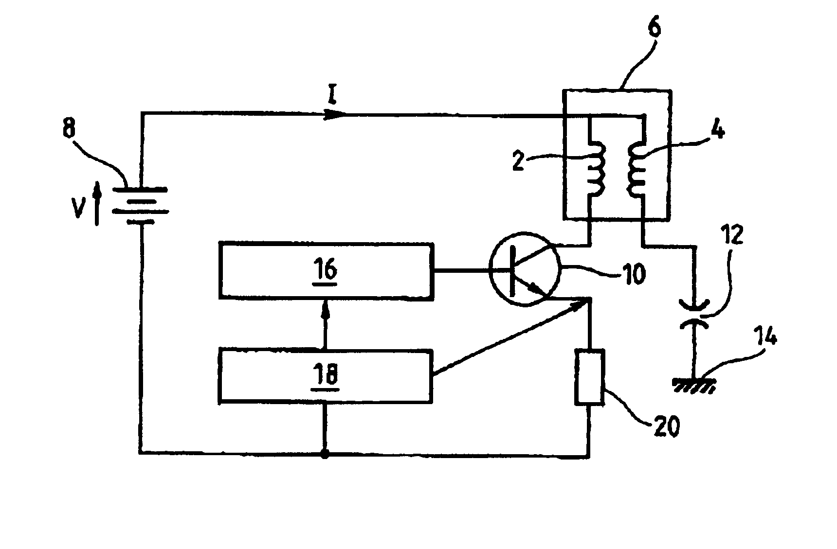
[0027]FIG. 1 schematically represents an ignition device for an internal combustion engine with controlled ignition. This figure shows a conventional ignition coil. This coil has a primary winding 2 also commonly referred to as the “primary”, and a secondary winding 4 commonly referred to as the “secondary”. These two windings interact with one another so as to form a step-up voltage transformer 6.

[0028]The primary winding 2 is supplied by a voltage source 8, which is usually the battery of the vehicle in question. A switch 10, which here is in the form of a transistor, controls the electrical supply of the primary winding 2.

[0029]The secondary winding 4 has one terminal in common with the primary winding 2. The other terminal of the secondary winding 4 is connected to an electrode of a spark plug 12, the other electrode of this spark plug being connected to the ground 14.

[0030]A spark is produced when a large potential difference is formed between the electrodes of the spark plug 1...


PUM


Abstract

Method for controlling a primary current in an ignition coil of an internal combustion engine with controlled ignition, the current is established in an inductive primary circuit over a given conduction time. The conduction time is calculated by:predetermining the predetermined conduction time,carrying out at least one measurement of the current in the primary circuit at an instant lying in the last tenth of the predetermined conduction time;estimating the current at the end of the predetermined conduction time, as a function of the measurement(s) carried out;optionally correcting the conduction time for the ignition cycle during which the last current measurement was carried out, as a function of the previous estimate and the current desired at the end of the conduction time.

Description

BACKGROUND OF THE INVENTION[0005]The present invention relates to a method for controlling the primary ignition current in an internal combustion engine with controlled ignition.[0006]In such an engine, a fuel / oxidant mixture is ignited with the aid of a spark in order to cause a driving explosion. The spark is produced by a spark plug. The latter has two electrodes, between which an electric arc is induced in order to form the spark. A fairly large potential difference is required between the electrodes in order to be able to create an arc, but it is also necessary for a current to flow between the electrodes in order to supply enough energy to the fuel / oxidant mixture and ignite it.DESCRIPTION OF THE RELATED ART[0007]Conventionally, the large potential difference across the terminals of the electrodes of the spark plug is obtained by breaking the current in a circuit that has a primary winding, and by amplifying the overvoltage which results therefrom in a secondary winding. A cur...

Claims


Application Information

Patent Timeline
IPC IPC(8): F02P3/02F02P3/05F02P3/045F02P3/055
CPCF02P3/0456F02P3/051F02P3/0554
Inventor GEOFFROY, YVES
Owner SIEMENS VDO AUTOMOTIVE CORP
Learn More