[0005]It is the object of the present invention to avoid the aforenoted disadvantages and to provide a
system of heddles with damping or
cushioning elements that permit proper operation of the loom shaft even at high weaving
machine speeds and preferably utilizing loom shafts of traditional design.
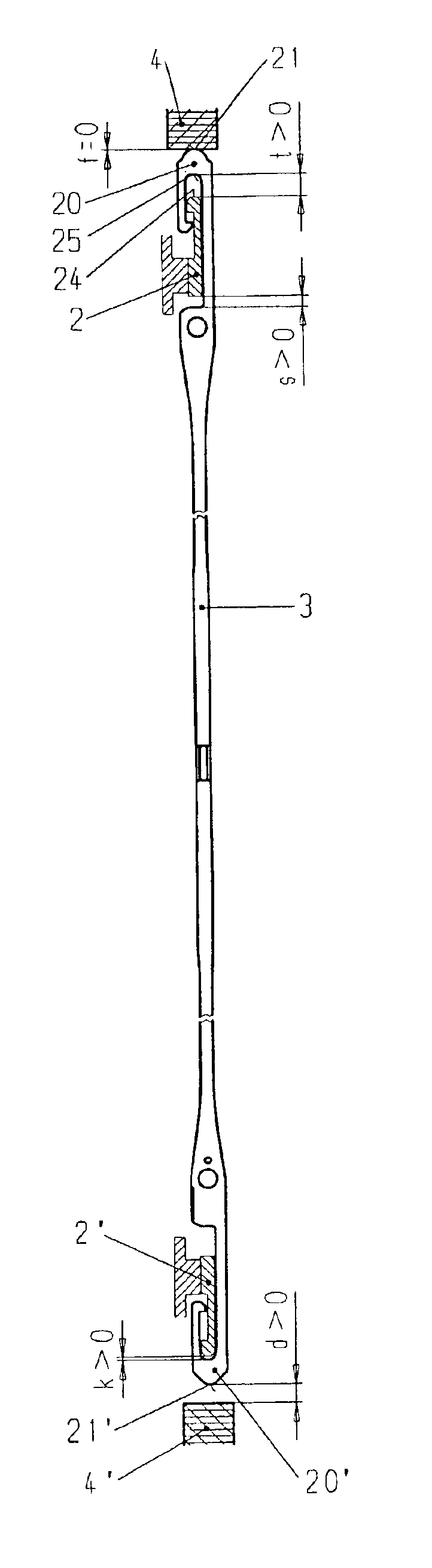
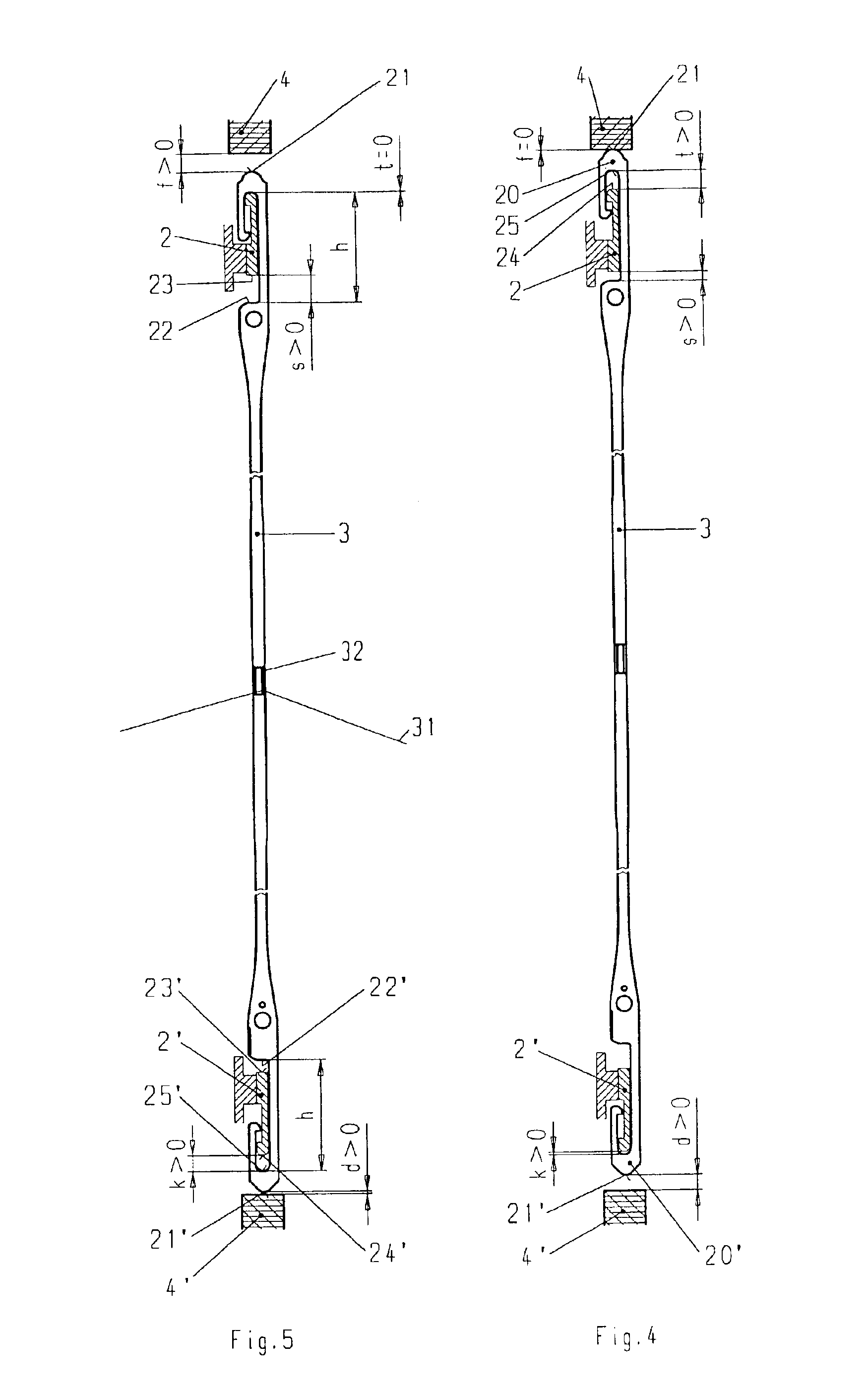
[0008]A heddle is provided according to the invention that deviates from the norm and allows swaying of the loom shafts without making contact of the inner edge of the heddle support rail with the heddles themselves. Additionally, the damping or
cushioning is provided in such a manner that it prevents over-shooting of heddles relative to the heddle support rails and thereby the heddles may preferably be exchanged in an easy manner. The latter is of significance since the damping element inevitably becomes a worn part and has to be replaced from time to time.
[0012]The damping element added in accordance with the invention may be made of a relatively hard, rubber-like elastic material. The
hardness should amount to more than 80
Shore, preferably 90 to 95
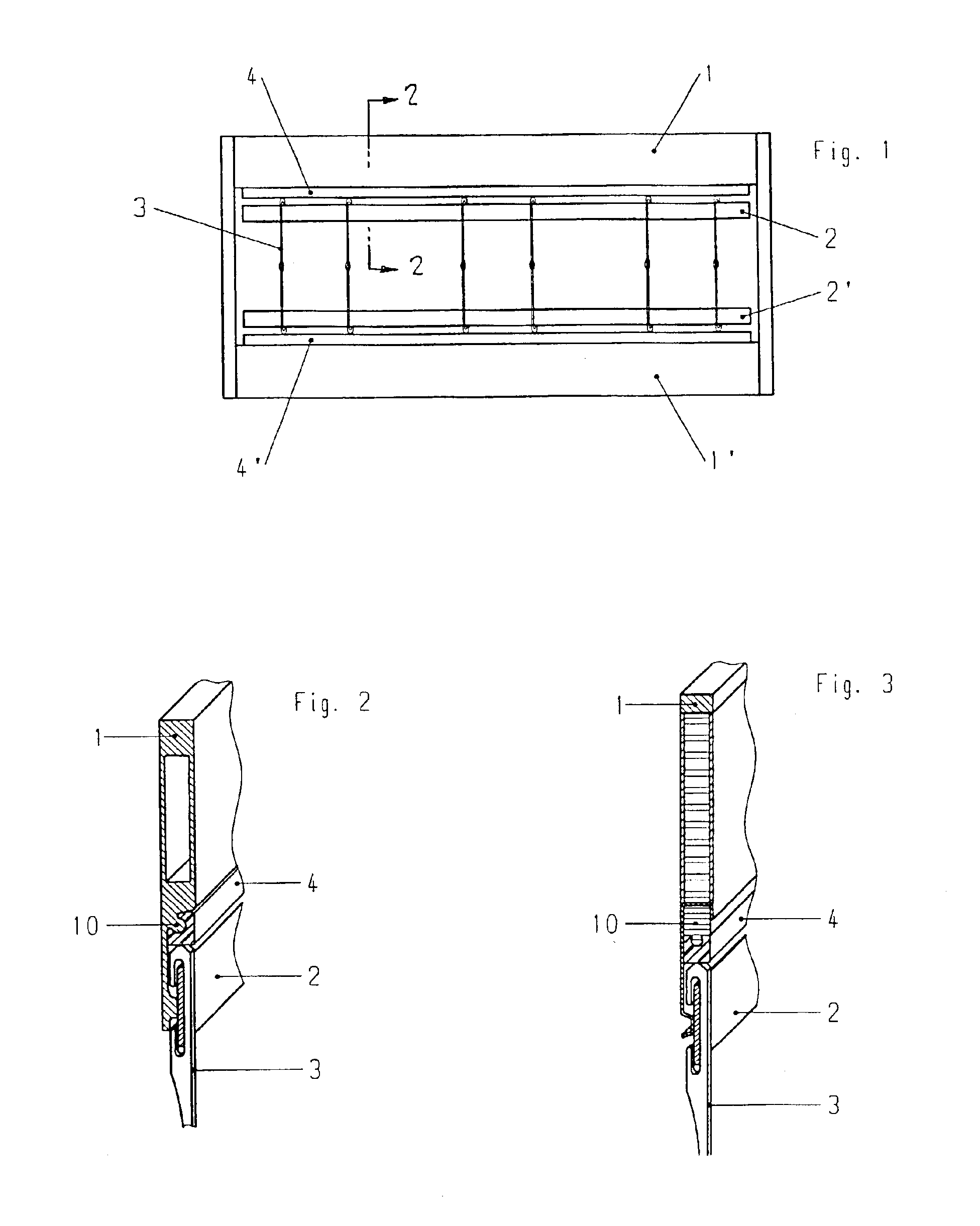
Shore. The damping elements may be designed in such a manner as to be snapped onto to a projection provided on the shaft profile. This allows a simple exchange in a time saving manner of the damping element worn down during operation and may be installed without the use of tools. The cross-section of the damping element, which may be attached by snapping, may change in shape in a manner whereby the aforementioned limitation of
free movement of the heddle can be controlled according to needs and whereby the full cross-section is to be provided. Since the damping elements are interchangeable, damping elements having varying cross-sectional shapes can be provided and thereby experiment with a varying degree of
free movement to identify the optimum
operating point.
[0013]The mounting element is preferably designed as a projection. However, it is also possible to design the mounting element in the form of a groove. The mounting element, which is to be pushed into the groove for attachment, is in such case, formed on the damping element itself and the function of the damping element remains the same as aforementioned. The design of such a mounting element on the support bar of a loom shaft is very simple whereby the support bar is made of aluminum. The mounting element is formed during
extrusion as part of the profile. The
machining of such a mounting element may not be so easy in shafts that are made of steel parts or in shafts made entirely or partly of
fiber-reinforced synthetic material. In cases where support bars are made of aluminum, there can be reasons for not extruding a holding element on the support profile, for example, the attachment of an intermediate brace. In such cases, a separate support element made of light material, preferably synthetic material, is fastened to the shaft preferably by gluing. This support element is shaped to fit the respective support bar and is provided with a projection or groove in the same manner as aforedescribed and it serves thereby as a mounting element for the damping element of the invention. As a whole, the invention has the effect that a heddle has been provided that is pulled by the heddle support bar when it has to be accelerated, and it is thereby provided with a stabilized position and does not tend to turn sideways. The novel heddle according to the invention can freely oscillate between the two heddle support rails at jolting accelerations so that the inner sides of the end eyes do not come into contact with the heddle support rails, not even then when the distance between the heddle support rails is considerably decreased by the bending of shafts since the damping element comes into action at this point. Moreover, the thusly created heddle cooperates with the damping element, according to the invention, by the change and the shape of the end eye of the heddle whereby wear of heddles and heddle support rails is radically decreased. As a result, the operational life of heddles and shafts are increased and production stops are avoided during weaving.
[0014]Independent of the design of the end eyes of the heddles and the heddle support rails for further use, it is advantages according to the invention that the two end eyes be provided with
free movement in the direction toward the thread eye surpassing the degree of movement relative to the heddle support rail as defined in the Standards and surpassing mere functional necessity. The inventive cooperation of the novel heddle and damping element is only made possible by the aforedescribed arrangement. The heddle according to the invention may be also employed without a damping element, if the tension of the warp thread running through the warp eye is sufficiently high. In such case, it may be that the end eye, which has not been in contact with the heddle support rail originally and which is the end eye opposite the end eye taking up the acceleration of the heddle, comes into contact with the opposite heddle support rail. Under such circumstances, this may be sufficient to ensure acceptable operation of the weaving
machine. In a preferred version of an inventive embodiment, the
system of the damping element will always be employed since a
noise-reducing effect is additionally achieved through the use of the damping element. However, since the damping elements do wear down inevitably with time, and any rubbed-off material particles fall, at least partly, onto the warp threads, there are some woven fabrics for which the employment of damping elements is highly undesirable due to such
contamination. It is therefore an additional
advantage of the novel heddle in that it may also be employed together with loom shafts on which the attachment of the damping element is not possible for geometrical reasons or where it is unacceptable based on its
contamination, and a wear-reducing effect is still achieved.

