Structuring air duct

a technology of air ducts and structures, applied in vessel construction, roofs, manufacturing tools, etc., can solve problems such as mechanical strength weakness, structural air ducts to be bent, and mechanical strength not entirely satisfactory, so as to improve the mechanical improve the strength of the ducts

Inactive Publication Date: 2005-04-26
FAURECIA INTERIEUR IND
View PDF8 Cites 9 Cited by
  • Summary
  • Abstract
  • Description
  • Claims
  • Application Information

AI Technical Summary

Benefits of technology

[0034]In order further to improve the strength of the duct, the invention proposes that the duct also comprises, in said end region of the stop elements, at least one weld seam connecting the two

Problems solved by technology

Although such a solution provides sealing between the two half-shells, it is not entirely satisfactory as regards mechanical strength in the case of impact.
The applicant has noticed that the continuous weld seam has the advantage over a discontinuous weld (for example an ultrasonic weld, which is constituted by a succession of spots) of providing sealing between the half-shells but that it also has a weakness in terms of mechanical strength.
This is particularly true in the case of front impact where the front supports of the vehicle have a tendency to move towards one another and to cause the structuring air duct to be bent.
consequently, the solution indi

Method used


Image

  • Structuring air duct
  • Structuring air duct
  • Structuring air duct

Examples


Embodiment Construction

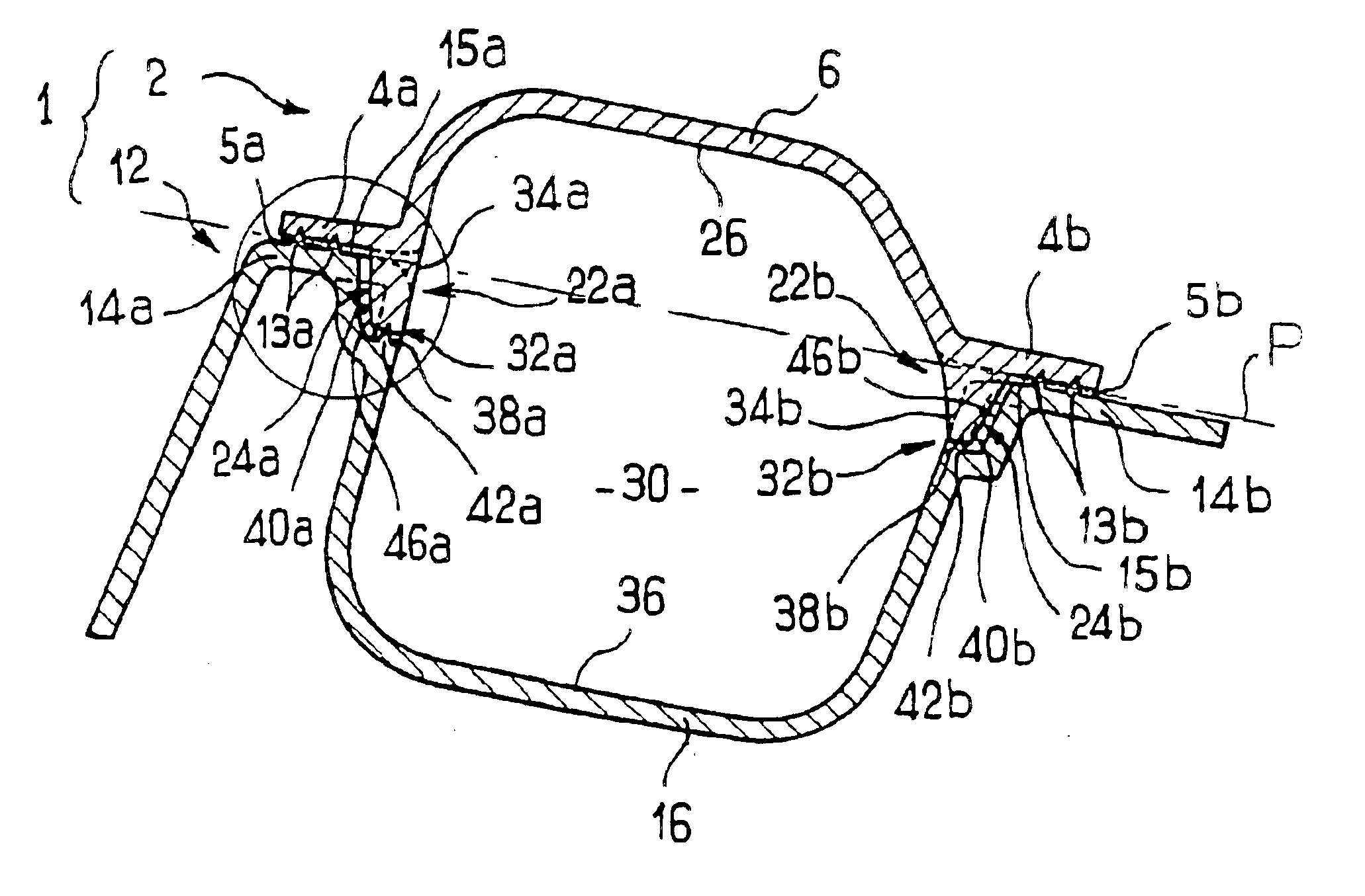
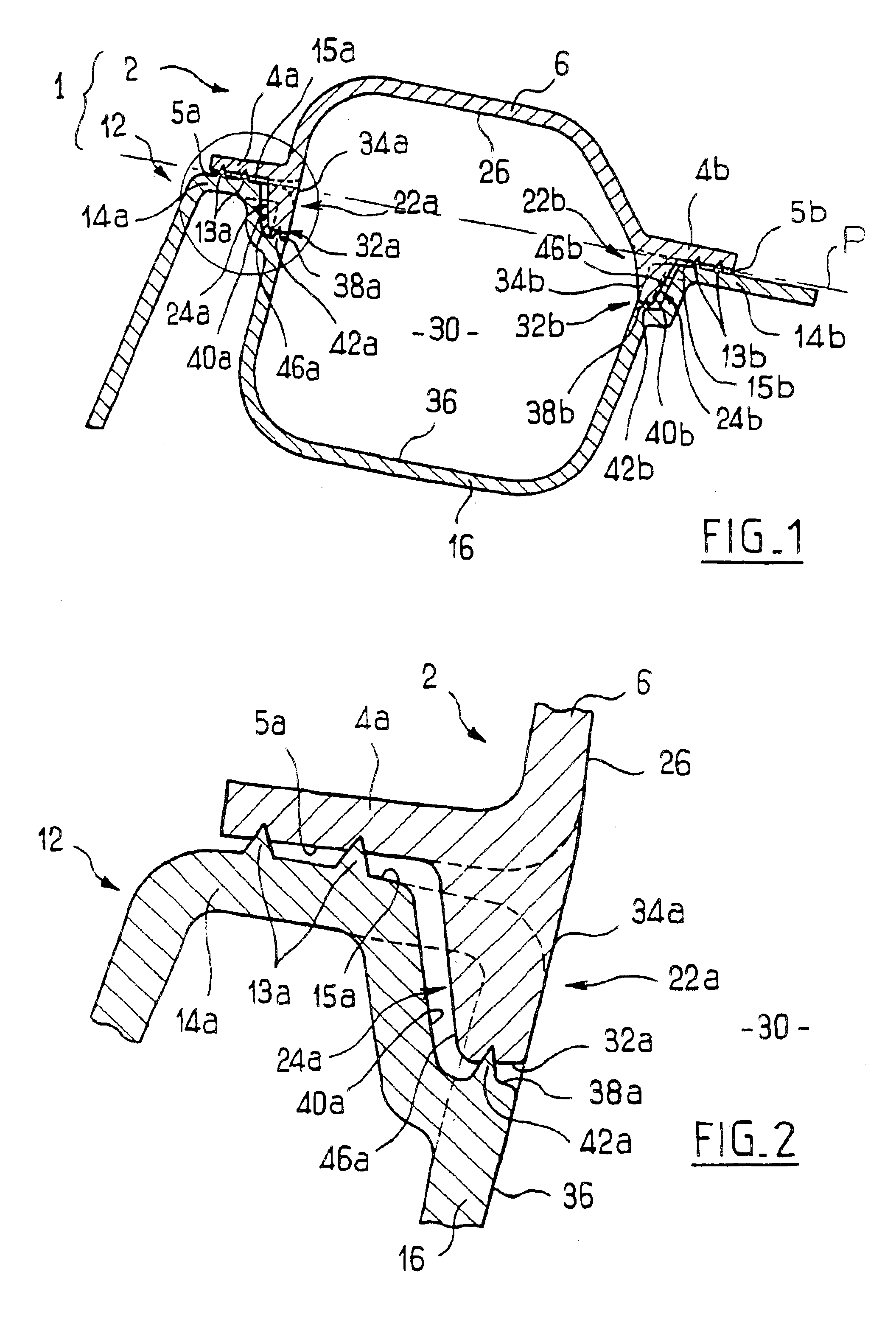
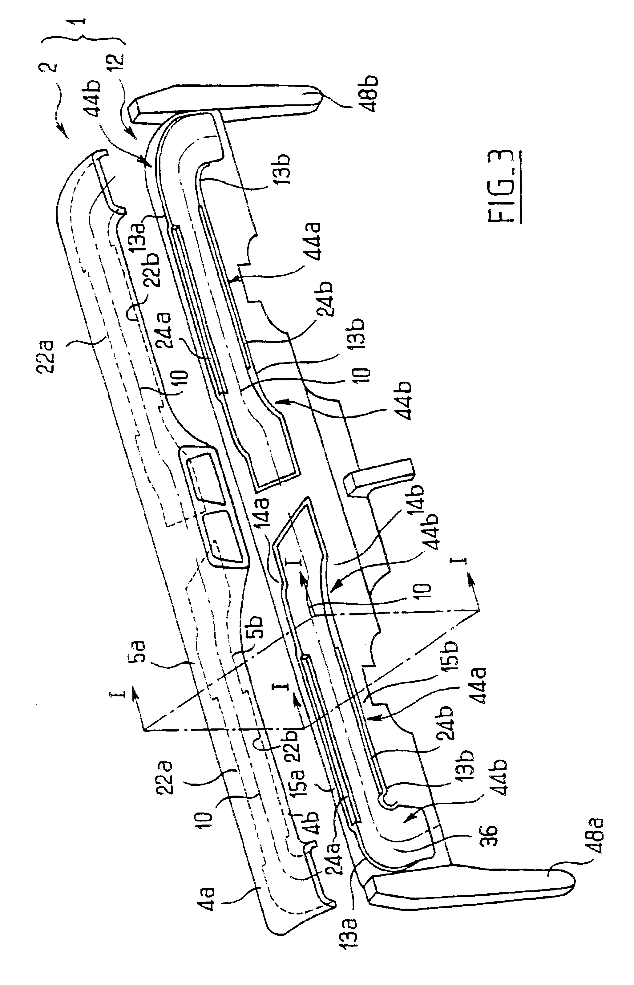
[0048]FIGS. 1 to 3 illustrate a duct 1 comprising an upper half-shell 2 and a lower half-shell 12 extending in a direction of elongation 10. Each half-shell 2, 12 comprises a front flank, upper 4a and lower 14a respectively, a rear flank, upper 4b and lower 14b respectively, and a tubular portion, upper 6 and lower 16 respectively, extending between the respective front and rear flanks. The tubular portions 6, 16 have an internal surface 26, 36 delimiting an air cavity 30, in this case in two parts.

[0049]The upper front flank 4a has a front upper surface 5a in contact with a front lower surface 15a belonging to the front lower flank 14a, while the upper rear flank 4b has a rear upper surface 5b in contact with a rear lower surface 15b belonging to the rear lower flank 14b. All these contact surfaces 5a, 5b, 15a, 15b are substantially flat and extend in a substantially horizontal plane P containing the direction of elongation 10.

[0050]The fact that the plane P is substantially horizo...


PUM


Abstract

The invention concerns a motor vehicle air duct also serving as crosspiece forming part of the structure of the vehicle. The invention is characterised in that the duct comprises two half-shells (2, 12) including each a tubular portion (6, 16) and two lateral flanks (4a, 4b; 14a, 14b); it further comprises: two stop elements (22a, 22b) defining each a rib projecting relative to one of the contact surfaces of one of the half-shells and having a stop surface arranged immediately proximate to an abutting surface (40a, 40b) provided on the other half-shell (12), a continuous weld bead (13a, 13b) extending between the contact surfaces of the half-shells which are in contact with each other.

Description

BACKGROUND OF THE INVENTION[0001]The invention relates to an air duct of a motor vehicle.[0002]The invention relates more precisely to an air duct of the structuring type, which supports some of the forces to which the vehicle is subjected, the air duct acting in particular also as a crosspiece forming part of the structure of the vehicle and supporting various accessories.[0003]The invention aims to provide, in a simple, reliable and inexpensive manner, an air duct having a high degree of mechanical strength and satisfactory sealing with respect to the air that has to circulate inside it.[0004]As indicated in the introductory part of FR-A-2 796 577, it is known to produce a motor vehicle air duct extending in a direction of elongation and comprising two half-shells arranged opposite one another, such that each half-shell has:[0005]a tubular portion extending in the direction of elongation of the duct, the tubular portions defining between them an air cavity extending in said direct...

Claims


Application Information

Patent Timeline
IPC IPC(8): B60H1/00
CPCB60H1/00564B60H1/242
Inventor LABORIE, JEAN-MICHELDUCHEZ, DAVID
Owner FAURECIA INTERIEUR IND
Why Eureka
Try Eureka