Fabricating biopolymer arrays

a technology of biopolymer arrays and polynucleotides, applied in the field of polynucleotide arrays, can solve the problem of slow loading process without the benefit of negative pressure assist, and achieve the effect of easy purging and cleaning of the jets and easy loading of the head

Inactive Publication Date: 2005-04-26
AGILENT TECH INC
View PDF26 Cites 68 Cited by
  • Summary
  • Abstract
  • Description
  • Claims
  • Application Information

AI Technical Summary

Benefits of technology

[0010]The present invention then, recognizes that by providing a backpressure of predefined value to a pulse jet, loading can be accomplished by drawing liquid through the orifice with a low likelihood of air entering the orifices to result in loss of prime in the jet. The same system can also allow for easy purging and cleaning of the jets. In another aspect, the present invention further realizes that regions around and outside jet orifices can be cleaned while preventing cleaning fluid from entering the jets, by providing a positive pressure to the jets.
[0016]Apparatus and methods of the present invention provide for easy loading of the head through the jet orifices, while providing a low opportunity for ambient atmosphere (air or otherwise) to enter the orifices after loading to result in loss of prime in the jets. Such apparatus and methods can also provide easy purging and cleaning of the jets. In particular they can provide cleaning of the regions around an outside of the jet orifices without using sprayed liquids, while inhibiting cleaning fluid from entering the jets during the cleaning operation.

Problems solved by technology

The load pressure is simultaneously insufficient to result in ambient atmosphere entering the delivery chamber through the orifice once the head has been loaded and no further fluid is facing and adjacent the orifice.
However, loading will proceed more slowly without the benefit of a negative pressure assist of the defined value.

Method used


Image

  • Fabricating biopolymer arrays
  • Fabricating biopolymer arrays
  • Fabricating biopolymer arrays

Examples


Embodiment Construction

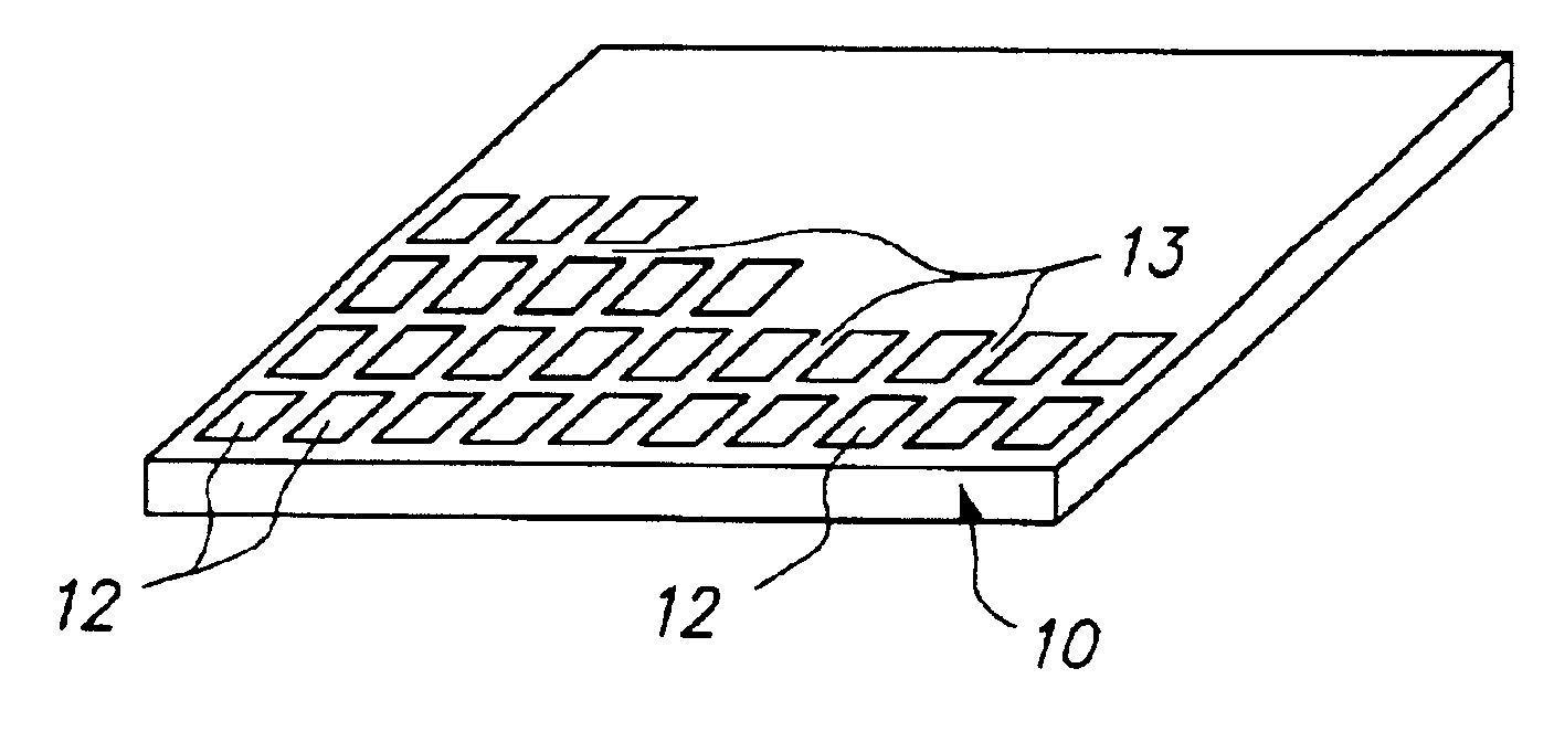
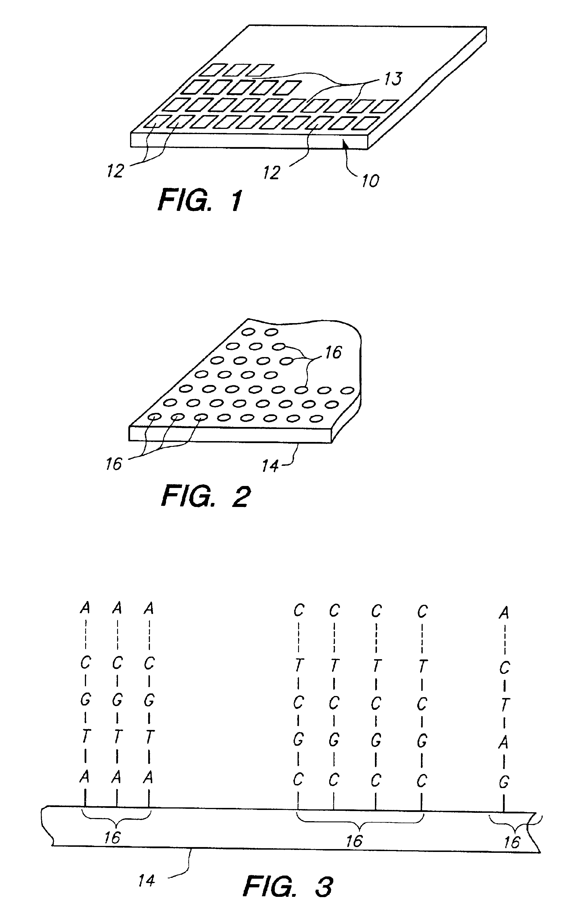
[0028]In the present application, unless a contrary intention appears, the following terms refer to the indicated characteristics. A “biopolymer” includes peptides or polynucleotides, as well as such compounds composed of or containing amino acid or nucleotide analogs or non-nucleotide groups. This includes those compounds in which the conventional polynucleotide backbone has been replaced with a non-naturally occurring or synthetic backbone, and those a nucleic acid in which one or more of the conventional bases has been replaced with a synthetic base capable of participating in Watson-Crick type hydrogen bonding interactions. Polynucleotides include single or multiple stranded configurations, where one or more of the strands may or may not be completely aligned with another. A “nucleotide” refers to a subunit of a nucleic acid and includes a phosphate group, a 5 carbon sugar and a nitrogen containing base, as well as analogs of such subunits. Specifically, a “biopolymer” includes ...


PUM

PropertyMeasurementUnit
pressureaaaaaaaaaa
exit diameteraaaaaaaaaa

Abstract

A method and apparatus for fabricating an array of biopolymers on a substrate using a biopolymer or biomonomer fluid, and using a dispensing head. The head has a reservoir chamber and at least one jet which can dispense droplets onto a substrate. The jet includes a capillary delivery chamber communicating with the reservoir chamber, which delivery chamber has an orifice. The jet further includes an ejector which, when activated, causes a droplet to be ejected from the orifice. The method includes loading the head by positioning the head with the orifice adjacent and facing a biomonomer or biopolymer fluid, and providing a load pressure to the reservoir chamber. The load pressure is sufficiently negative such that the fluid is drawn into the reservoir chamber through the orifice and delivery chamber, while simultaneously being insufficient to result in ambient atmosphere entering the delivery chamber through the orifice once the head has been loaded and no further fluid is facing and adjacent the orifice. The head is positioned with the orifice facing the substrate and multiple droplets are dispensed from the head orifice so as to form an array of droplets on the substrate.

Description

CROSS REFERENCE TO RELATED APPLICATIONS[0001]This application is a continuation of U.S. patent application Ser. No. 09 / 302,922 filed Apr. 30, 1999 by Caren et al. for “Fabricating Biopolymer Arrays”, now U.S. Pat. No. 6,323,043, from which priority is claimed under 35 U.S.C. 120. The foregoing application is incorporated herein by reference.FIELD OF THE INVENTION[0002]This invention relates to biopolymer arrays, particularly polynucleotide arrays such as DNA arrays, which are useful in diagnostic, screening, gene expression analysis, and other applications.BACKGROUND OF THE INVENTION[0003]Arrays of biopolymers, such as arrays of peptides or polynucleotides (such as DNA or RNA), are known and are used, for example, as diagnostic or screening tools. Such arrays include regions (sometimes referenced as spots) of usually different sequence biopolymers arranged in a predetermined configuration on a substrate. The arrays, when exposed to a sample, will exhibit a pattern of binding which i...

Claims


Application Information

Patent Timeline
Patent Type & Authority Patents(United States)
IPC IPC(8): B01J19/00C40B40/06C40B40/10C40B60/14
CPCB01J19/0046Y10T436/2575B01J2219/00527B01J2219/00585B01J2219/0059B01J2219/00596B01J2219/00605B01J2219/00608B01J2219/0061B01J2219/00612B01J2219/00617B01J2219/00619B01J2219/00626B01J2219/00637B01J2219/00659B01J2219/00722B01J2219/00725C40B40/06C40B40/10C40B60/14B01J2219/00378
Inventor CAREN, MICHAEL P.SCHEMBRI, CAROL T.WEBB, PETER G.
Owner AGILENT TECH INC
Why Eureka
Try Eureka