Controlled composition welding method

a composition welding and composition welding technology, applied in the direction of manufacturing tools, turbines, gearing, etc., can solve the problems of difficult manufacturing or fabrication of solid welding consumables (wires or strips), and achieve the effect of increasing the deposition rate of the weld process

Inactive Publication Date: 2005-04-26
ELECTRIC POWER RES INST INC
View PDF46 Cites 41 Cited by
  • Summary
  • Abstract
  • Description
  • Claims
  • Application Information

AI Technical Summary

Benefits of technology

[0013]The ability to tailor the composition of a weld provides benefits in the application of consumable alloys which are inherently difficult to fabricate. Solid welding consumables (wire or strip) are difficult to manufacture or fabricate in certain applications due to expense or technological limitations of drawing the consumable to a small diameter. The use of tailored compositions will help overcome this obstacle. Essentially, the present invention provides the ability to cast a desired consumable composition “in place.” Such an ability allows a weld composition to be tailored so that the material properties, such as corrosion resistance, hardness, or strength, of the weld are more suited for the designed function of a particular location on the workpiece. Adding filler directly to the weld puddle also increases the deposition rate of the weld process without complicating the maintenance of the arc or other weld puddle-forming procedures.

Problems solved by technology

Solid welding consumables (wire or strip) are difficult to manufacture or fabricate in certain applications due to expense or technological limitations of drawing the consumable to a small diameter.

Method used


Image

  • Controlled composition welding method
  • Controlled composition welding method
  • Controlled composition welding method

Examples


example 1

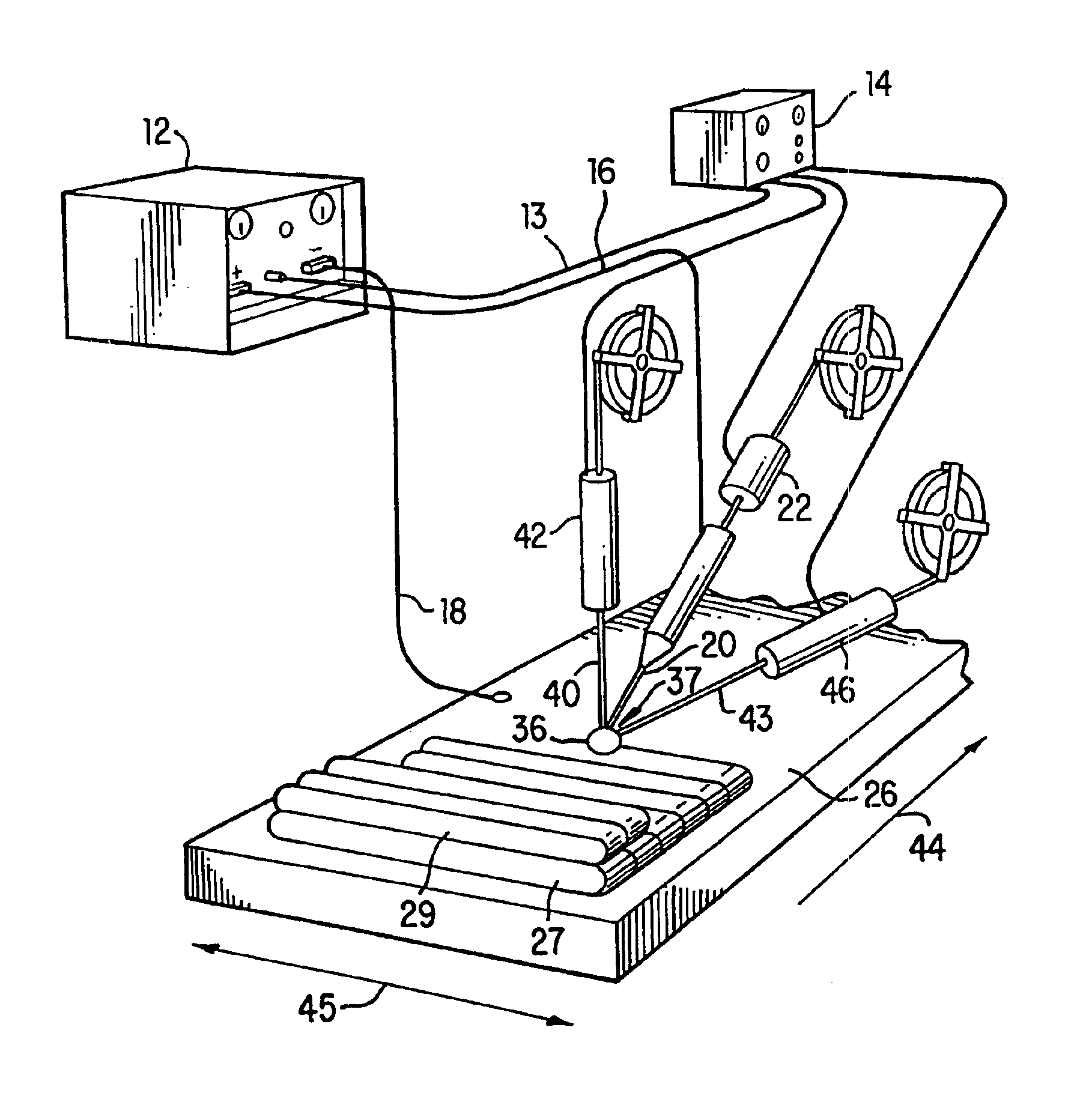
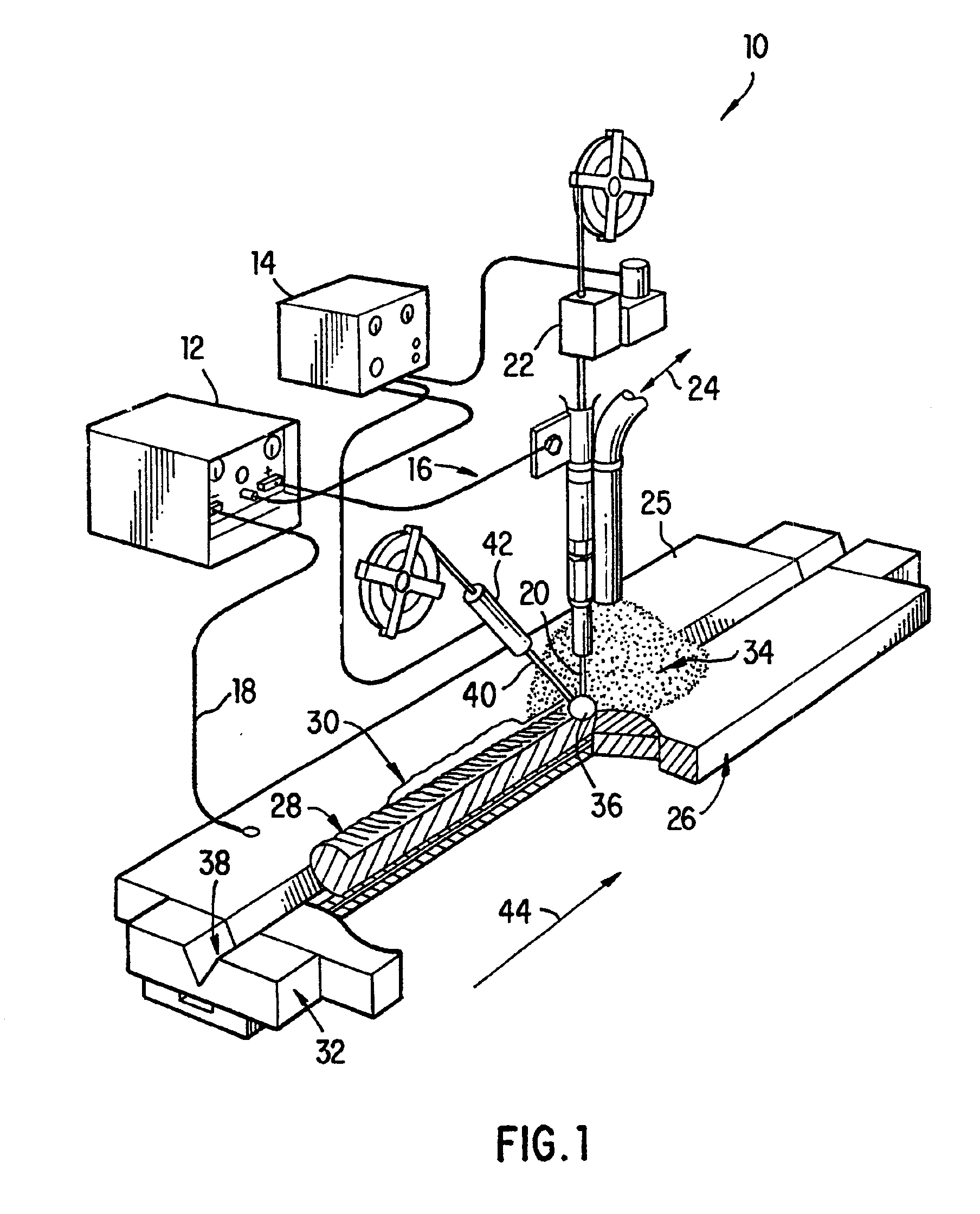
[0038]The following example describes the creation of a tailored weld composition in an exemplary embodiment according to the present invention. This example shows the method of the invention used to change the composition of a weld, with the weld created using a submerged arc welding technique and apparatus such as that illustrated in FIG. 1. Also, this example uses multiple filler wires, as depicted in FIG. 3, fillers 40 and 44, to change both weld composition and weld deposition rate. For the purposes of this example, only the Cr and Ni content and their changes will be discussed. It is important to note that the second filler (wire) used is considerably higher in Cr and lower in Ni than the 150003-1 strip filler. (See Table 1 for filler compositions.)

[0039]Now referring Table 2, we see that for a weld made with the strip filler 150003-1, and no secondary filler (Test Bead # P2B14), the Cr and Ni content are 0.28 and 2.45 wt. % respectively. (See Table 3.) If a single wire is add...


PUM

PropertyMeasurementUnit
anglesaaaaaaaaaa
compositionaaaaaaaaaa
weld deposition rateaaaaaaaaaa

Abstract

This invention relates to a method and apparatus for controlling the composition of a weld. More particularly it relates to welding using an electric circuit, thereby creating a weld puddle, and adding at least one filler that is electrically independent from the electric circuit to the weld puddle at a controllable rate to obtain a target weld composition. The filler can be added to the extent limited by practical weld puddle geometry and, thus, the method and apparatus also facilitate increased weld deposition rates.

Description

BACKGROUND OF THE INVENTION[0001]1. Field of the Invention[0002]The invention relates to a method for welding. More specifically, the invention is concerned with a method for welding that provides for increased control of the weld composition and an increased weld deposition rate.[0003]2. Description of the Related Art[0004]Welding is often not an ideal method of manufacture or repair. Achieving weld metal deposits to satisfy composition, material properties and production requirements cannot always be accomplished with readily available or off-the-shelf welding consumables. Special melts or lots of bare wire, rod, or fluxes can be obtained, but not without any combination of impediments, such as observing minimum quantities, extended lead times, and premium prices. Due to manufacturing restrictions certain chemical composition or mechanical requirements cannot even be achieved with special consumables. Desires to increase production deposition rates are commonly thwarted by complex...

Claims


Application Information

Patent Timeline
Patent Type & Authority Patents(United States)
IPC IPC(8): B23K9/18
CPCB23K9/188B23K2201/008B23K2201/001B23K2101/001B23K2101/008
Inventor GANDY, DAVID WAYNEHALES, JAMES WILLIAMNEWELL, JR., WILLIAM FREDERICKSWAIN, ROGER ALLENTURNER, JAMES FRANKLINVISWANATHAN, RAMASWAMY
Owner ELECTRIC POWER RES INST INC
Why Eureka
Try Eureka