Diffractive optical position detector

a detector and optical position technology, applied in the direction of material analysis using wave/particle radiation, instruments, nuclear engineering, etc., can solve the problems of mechanical changes in micromechanical components, limited use of multiple beam sensor arrays in any number of commercial applications, and loss of optical power and spurious interference effects, so as to optimize the sensitivity of optical levers and minimize the effect of lost optical power

Inactive Publication Date: 2005-04-26
OXFORD INSTRUMENTS +1
View PDF7 Cites 22 Cited by
  • Summary
  • Abstract
  • Description
  • Claims
  • Application Information

AI Technical Summary

Benefits of technology

[0012]Diffractive Optical Elements (DOEs) provide a flexible and powerful means for splitting the beam from a single source of light into multiple beams and varying the intensity and shape of each beam. Using a DOE it is possible to illuminate an array of cantilevers or other mechanical structures using only one light source. The spacing between the focused spots and the spot geometry can be controlled. The multiple beams can also be shaped to vary the sensitivity of the measurement and the beams can be steered either individually or as a group.
[0013]Shaping the spot has important co...

Problems solved by technology

This complexity has limited the use of multiple beam sensor arrays in any number of commercial applications including high throughput scanning probe microscopes or micromechanical sensors containing numerous sensing elements and control levers for background measurements.
One challenge of a multiple sen...

Method used


Image

  • Diffractive optical position detector
  • Diffractive optical position detector
  • Diffractive optical position detector

Examples


Embodiment Construction

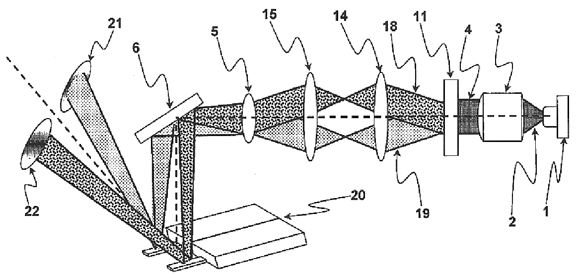
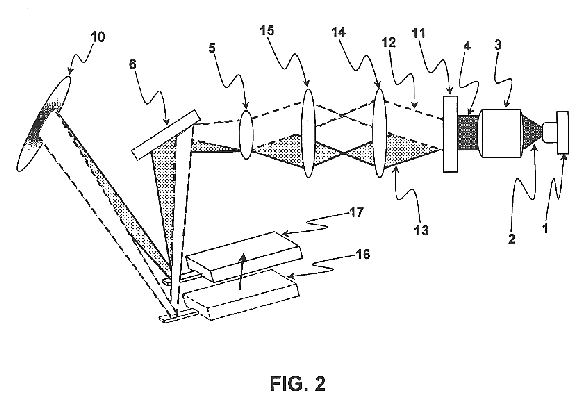
[0030]FIG. 2 shows an optical detector for an AFM using a DOE according to the invention disclosed herein. The purpose of this embodiment is to redirect an incident beam onto the cantilever as the cantilever moves, for example, as it scans over a surface relative to the optical assembly, where the cantilever and the optical detector are in different reference frames. Previous schemes devised to solve the problems presented by AFMs which decouple the cantilever and the optical detector have employed conventional optical technology. The most successful, based on a tracking lens that moves with the piezo tube scanning the cantilever, is described in U.S. Pat. No. 6,032,518. A major disadvantage of this and other schemes to deal with these problems is that they require the optical elements to be carried along with the cantilever. This adversely affects the AFM performance by requiring time consuming and imperfect factory adjustments of the optical elements to optimize the tracking perfo...


PUM


Abstract

An apparatus and method for measuring optically the position or angle of a variety of objects or arrays of objects, including cantilevers in scanning probe microscopy, micromechanical biological and chemical sensors and the sample or a probe in surface profilometry. The invention involves the use of one or more diffractive optical elements, including diffraction gratings and holograms, combined with conventional optical elements, to form a plurality of light beams, each with a selectable shape and intensity, from a single light source, reflect the beams off mechanical objects and process the reflected beams, all to the end of measuring the position of such objects with a high degree of precision. The invention may also be used to effect mechanical changes in such objects. Devices with these improvements have numerous applications, including molecular force measurements, atomic force microscopy and manipulation technology, lithographic manufacturing, nanometer scale surface profiling and other aspects of nanotechnology.

Description

CROSS-REFERENCE TO RELATED APPLICATIONS[0001]This application claims priority of U.S. Provisional Application No. 60 / 314,075, filed on Aug. 23, 2001, the disclosures of which are incorporated fully herein by reference.REFERENCES CITEDU.S. PATENT DOCUMENTS[0002]4,669,300March 1984Hall et al. 3 / 1055,477,383December 1995Jain359 / 5655,825,020October 1998Hansma et al.250 / 2166,032,518March 2000Prater et al. 73 / 1056,055,106April 2000Grier et al.359 / 566OTHER PUBLICATIONS[0003]Schaffer, T. E., et al., Characterization and Optimization of the Detection Sensitivity of an Atomic Force Microscope for Small Cantilevers, Jour. App. Physics, vol. 84, pp 4661-66 (1999).[0004]Altmann, Stephan M., et al., Multiple Sensor Stabilization System for Local Probe Microscopes, Rev. of Scientific Instruments, vol. 72, pp 142-9 (2001).[0005]Morgensen, Paul C., et al., Dynamic Array Generation and Pattern Formation for Optical Tweezers, Optics Communications, vol. 175, pp. 75-81 (2000).BACKGROUND AND SUMMARY OF ...

Claims


Application Information

Patent Timeline
IPC IPC(8): G12B21/08G12B21/00G12B21/02G01Q20/02G01Q60/24
CPCB82Y35/00G01Q70/06G01Q20/02G02B26/0808
Inventor PROKSCH, ROGERCLEVELAND, JASONBOCEK, DAN
Owner OXFORD INSTRUMENTS
Why Eureka
Try Eureka