Class E amplifier with inductive clamp
a clamping and amplifier technology, applied in the direction of power conversion systems, electrical equipment, electric discharge tubes, etc., can solve the problems of high transistor power dissipation, poor efficiency, and disadvantages of fig. 1
- Summary
- Abstract
- Description
- Claims
- Application Information
AI Technical Summary
Benefits of technology
Problems solved by technology
Method used
Image
Examples
Embodiment Construction
[0045]The following description of the preferred embodiment(s) is merely exemplary in nature and is in no way intended to limit the invention, its application, or uses.
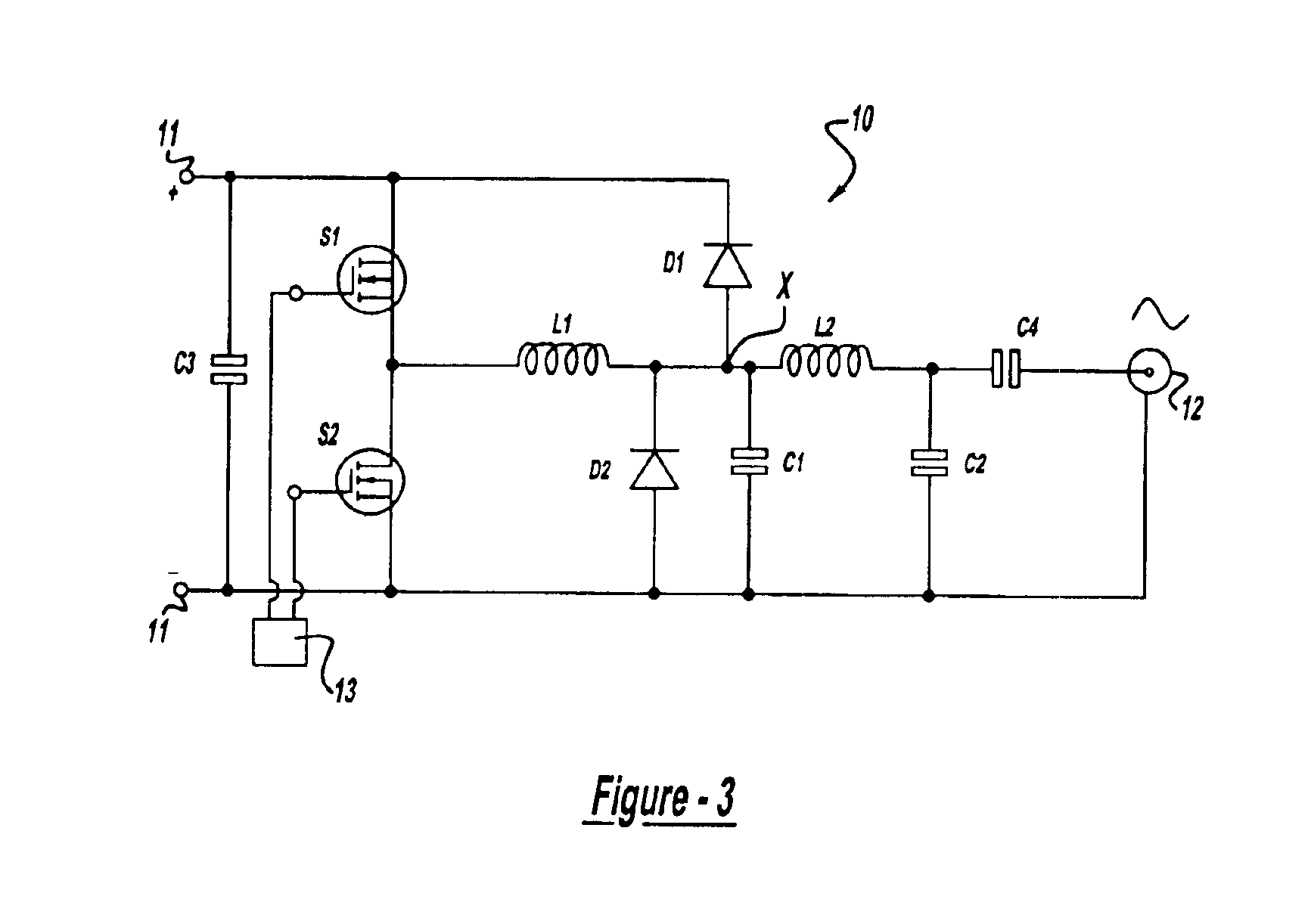
[0046]With reference to FIG. 3, a voltage inverter circuit is generally indicated at 10 and has a direct current (DC) voltage source input at 11 and an alternating current (AC) output at 12. It should be noted from the outset that in describing the figures, switches will generally be referred to using S followed by a number; capacitors will be referred to using C followed by a number; inductors will be referred to using L followed by a number; diodes will be referred to using D followed by a number; and transformers will be referred to using T followed by a number. Further, in circuits which have a generally symmetric topology, each of the above reference symbols may be followed by a letter suffix to indicate generally similar, symmetric elements.
[0047]Switches S1, S2 receive as input respective out of phase square wa...
PUM
 Abstract
Description
Claims
Application Information
 - R&D
- Intellectual Property
- Life Sciences
- Materials
- Tech Scout
- Unparalleled Data Quality
- Higher Quality Content
- 60% Fewer Hallucinations
Browse by: Latest US Patents, China's latest patents, Technical Efficacy Thesaurus, Application Domain, Technology Topic, Popular Technical Reports.
© 2025 PatSnap. All rights reserved.Legal|Privacy policy|Modern Slavery Act Transparency Statement|Sitemap|About US| Contact US: help@patsnap.com


