
Traveling highline system

a high-line, high-speed technology, applied in the direction of rope railways, transportation and packaging, ways, etc., can solve the problems of limited payload, small support structure, inconceivable control of movement, etc., and achieve the effect of moving objects

Inactive Publication Date: 2005-05-03
FORTRESS CREDIT CORP AS AGENT
View PDF53 Cites 20 Cited by
  • Summary
  • Abstract
  • Description
  • Claims
  • Application Information

AI Technical Summary

Benefits of technology

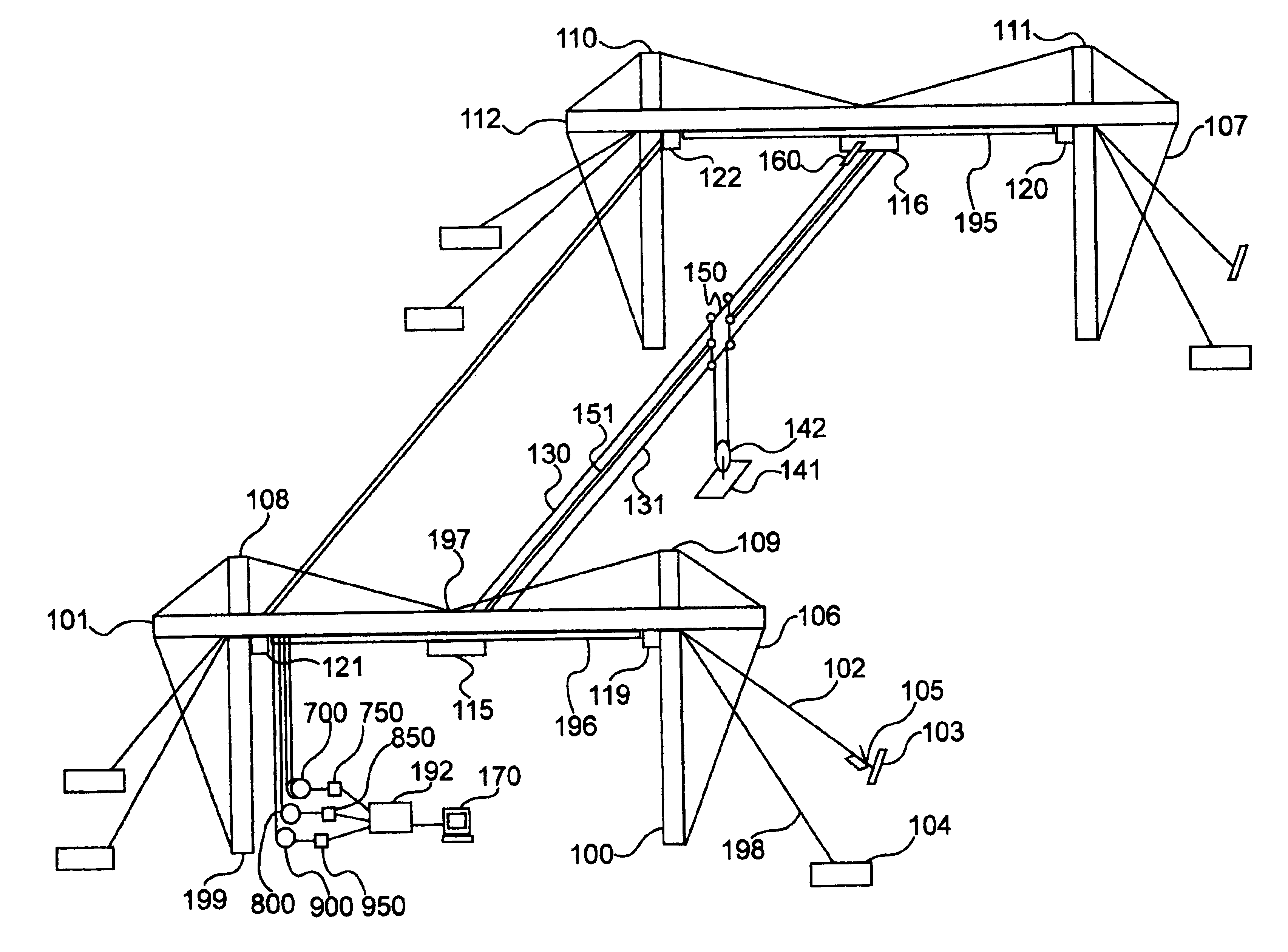
[0009]The invention is a traveling highline aerial cable rail system. A highline system is a system based on an elevated cable or rope, along which objects are transported. Embodiments of the invention can move objects throughout three-dimensional space quickly, accurately and stably by laterally moving the entire highline, each end of which coupled with a horizontal highline vehicle, or “track dolly” for short. Each track dolly is coupled with and travels in the direction defined by an associated track. The track is coupled with an associated horizontal support structure, or “truss” for short, that may or may not be completely parallel with the track. The system comprises a plurality of tracks, the most distantly separated two of which are substantially parallel. Movement of the track dollies associated with a highline provides movement of the highline and its payload in a direction defining the X-axis direction. Movement of a vertical support vehicle, or “skate” for short, in the direction of the highline provides for movement in a direction defining the Y-axis direction. Vertically moving a platform suspended from the skate provides for movement in a direction defining the Z-axis. Many types of useful devices may then be attached to the platform including devices that require external power or devices that possess their own power and are operated via wireless signals.
[0010]An embodiment of the invention uses a pair of coupled drive pulleys each of which control rope to their corresponding track dollies in order to move both track dollies simultaneously in the same amount along the X-axis, keeping the highline substantially parallel to the Y-axis. In this embodiment, another drive pulley independently controls the rope coupled with the skate, and a drum winch independently controls rope coupled with the platform. The ropes in this embodiment pass through multiple sheaves before finally reaching their intended recipients. By using sheaves that loop Y-axis and Z-axis ropes through the track dollies to the skate, Y-axis and Z-axis movement remains independent of X-axis traversal. When moving only in the X-axis direction, the skate sheaves and sheaves suspending the platform hence freely rotate, while maintaining a constant platform position in Y and Z space. Creating a three axis movement configuration from ropes driven from a point distantly located from the payload is non-trivial, but provides advantages of allowing the motors to be large, power cables to be short and located near a large generator and control computer and maintenance to be readily performed in one location. The Z-axis may also contain a pulley arrangement that multiplies the Z-axis travel, so that the full volume of space serviced is X*Y*N*Z, where N is the multiplication factor of the Z-axis pulley configuration.
[0017]Embodiments of the invention can stably move objects weighing thousands of pounds by utilizing heavy gauge rope that can support several tons, yet is extremely lightweight and pliable. The limit of weight carried can be scaled to any size by scaling the rope, trusses, track dollies and various other parts utilized. Embodiments of the invention utilize track dollies that move in the direction defined by tracks coupled with the trusses to keep the system from sagging inward under heavy loads, providing for more accurate positioning of the Z-axis platform that is independent of the X-axis position of the track dollies.
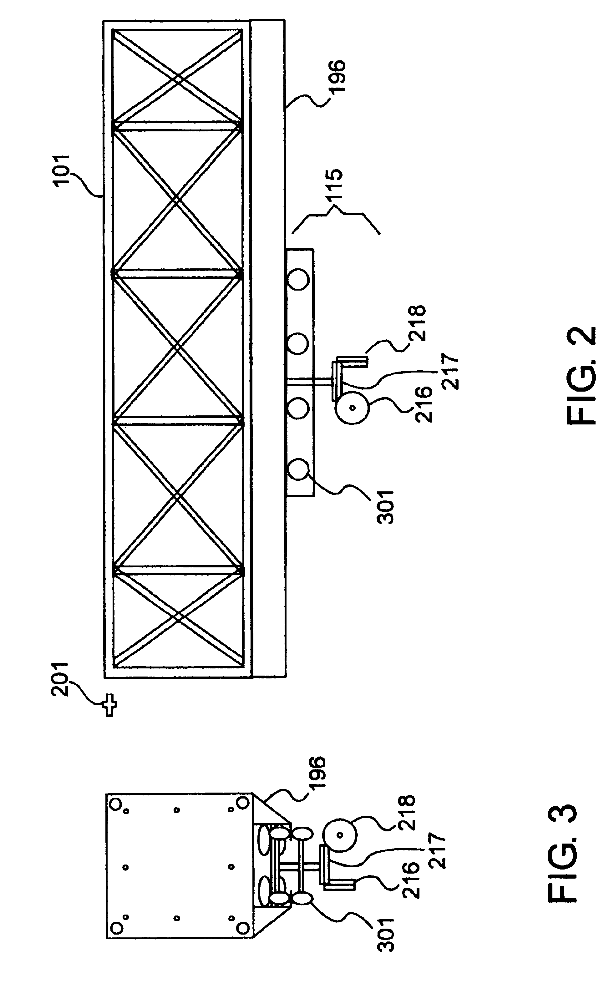
[0018]The system is configured to move objects across any axis by using motors mounted beneath the rigging, on or near the ground, to drive the ropes. These motors connect to a generator that can be as large as the application requires in order to produce the requisite payload speed. The system may, for instance, move objects at speeds up to 60 miles an hour or more. The reader should note, however, that lesser or greater speeds are attainable by modifying the size of motors used to control the ropes. The sheaves themselves may contain high speed bearings and are may be configured to capture the rope in order to prevent derailing in order to add a degree of safety to the system. The drive pulleys comprise grooves that grip the rope in order to prevent slippage, however any means of driving rope may be substituted for grooved pulleys. In embodiments of the invention where the track dollies comprise wheels, the wheels of the track dollies can be made from material that supports large amounts of weight, yet still allows for smooth X-axis travel.
[0020]Embodiments of the invention eliminate the problems associated with high winds by minimizing the area of the skate.

Problems solved by technology

Also, high winds would plague the system as the high surface area of the balloons would render controlled movement inconceivable.
The payload is limited and the support structure is small scale.
Also, the invention would not appear to allow the Z-axis to vary beneath the cube, and the size of the cube support structure to service a large volume of space would be extremely expensive to build on the scale required.
Mounting heavy motors high in the rigging presents a major safety issue given that suspension lines can break.
The size of the motors limits the payload that can be carried, and further limits the speed at which the payload can be carried.

Method used


Image

  • Traveling highline system
  • Traveling highline system
  • Traveling highline system

Examples


Embodiment Construction

[0030]The invention is a traveling highline aerial cable rail system. Embodiments of the invention can move objects throughout three-dimensional space quickly, accurately and stably by moving the highline itself laterally along two substantially parallel truss members, providing movement in the X-axis direction, while moving a skate along the highline in the Y-axis direction, and vertically moving a platform suspended from the skate in the Z-axis. Many types of useful devices may then be attached to the platform. In addition, the truss and track sections may be modular to allow for expansion in the X-axis.

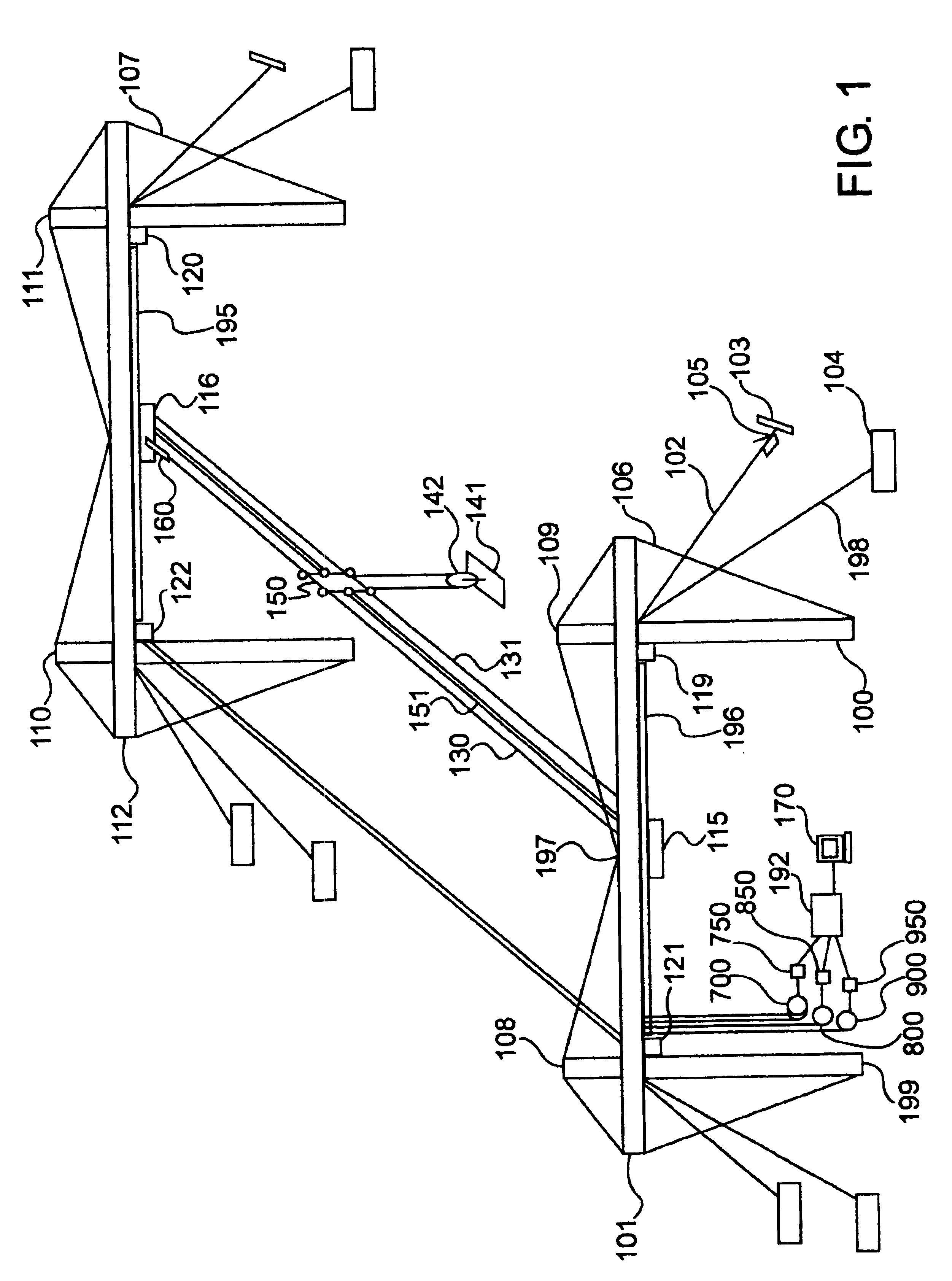
[0031]FIG. 1 shows a perspective view of an embodiment of the present invention. For the purpose of this discussion, the truss 101 forms the X-axis, the highline 130 forms the Y-axis of the system and the support structure 100 forms the Z-axis. In this configuration, vertical support structure 100 and 199 separates truss 101 from the terrain. The support structures are anchored to ...


PUM


Abstract

A traveling highline aerial cable rail system for moving objects over large distances in three-dimensional space. A pair of track dollies mounted beneath substantially parallel and distantly separated support trusses allow the entire load bearing highline itself to traverse X-axis space. The highline defines the Y-axis of the system and supports a skate that moves along this axis. A platform suspended from the skate moves vertically in the Z-axis and can support extremely heavy loads depending on the gauge of the rope used in the system. A three motor pulley system with a multiplicity of sheaves allow independent movement of all three axes. The system can move objects weighing thousands of pounds stably at 60 miles per hour or more through three-dimensional space. The system can be modularly widened along the X-axis by adding truss sections, and the highline can be configured to up to 1000 feet or more, using rope that can support several tons or more. The Z-axis displacement can be multiplied via a pulley arrangement.

Description

BACKGROUND OF THE INVENTION[0001]1. Field of the Invention[0002]This invention relates to a method and apparatus for moving objects within three-dimensional space. More specifically, the invention relates to a traveling highline aerial cable rail system.[0003]2. Description of the Related Art[0004]The controlled movement of heavy objects through large volumes of three-dimensional space has given rise to inventions that fail to satisfactorily achieve the full spectrum of speed, load bearing, volume serviced, extensibility, maintainability and platform stability. A “highline” system is a system based on an elevated cable or rope, along which objects are transported.[0005]According to the invention disclosed in U.S. Pat. No. 5,020,443, a highline invention is described which can haul heavy loads, but does not provide quick movement in the X-axis, since large tractors supporting the ends of the highline must be physically relocated. The tension on the highline can vary dramatically depe...

Claims


Application Information

Patent Timeline
IPC IPC(8): B61B7/00B61B7/04B66C21/00B66C21/04B66C11/00B66C11/16
CPCB61B7/00B66C21/04B66C11/16B61B7/045
Inventor RODNUNSKY, JAMES LEWIS
Owner FORTRESS CREDIT CORP AS AGENT
Learn More