Robust system for screening mail for biological agents

Inactive Publication Date: 2005-05-03
FLIR DETECTION
View PDF13 Cites 818 Cited by
  • Summary
  • Abstract
  • Description
  • Claims
  • Application Information

AI Technical Summary

Benefits of technology

[0028]Preferably, each sampler subsystem (triggering sampler, detecting sampler, and archiving sampler) uses a virtual impactor to concentrate the amount of particulates in a minor flow that is directed into the sampler subsystem. A virtual impactor performs the dual roles of drawing in air via a fan and concentrating the particulate matter via inertial flow splitting into the minor flow. Note that a virtual impactor is not strictly required, as less sophisticated embodiments could simply use a fan or other suitable means to draw air into the sampling subsystems. Thus, particulat

Problems solved by technology

Although a piece of mail can be contaminated both on the outer faces and on the inside, intentiona

Method used


Image

  • Robust system for screening mail for biological agents
  • Robust system for screening mail for biological agents
  • Robust system for screening mail for biological agents

Examples


Embodiment Construction

Overview

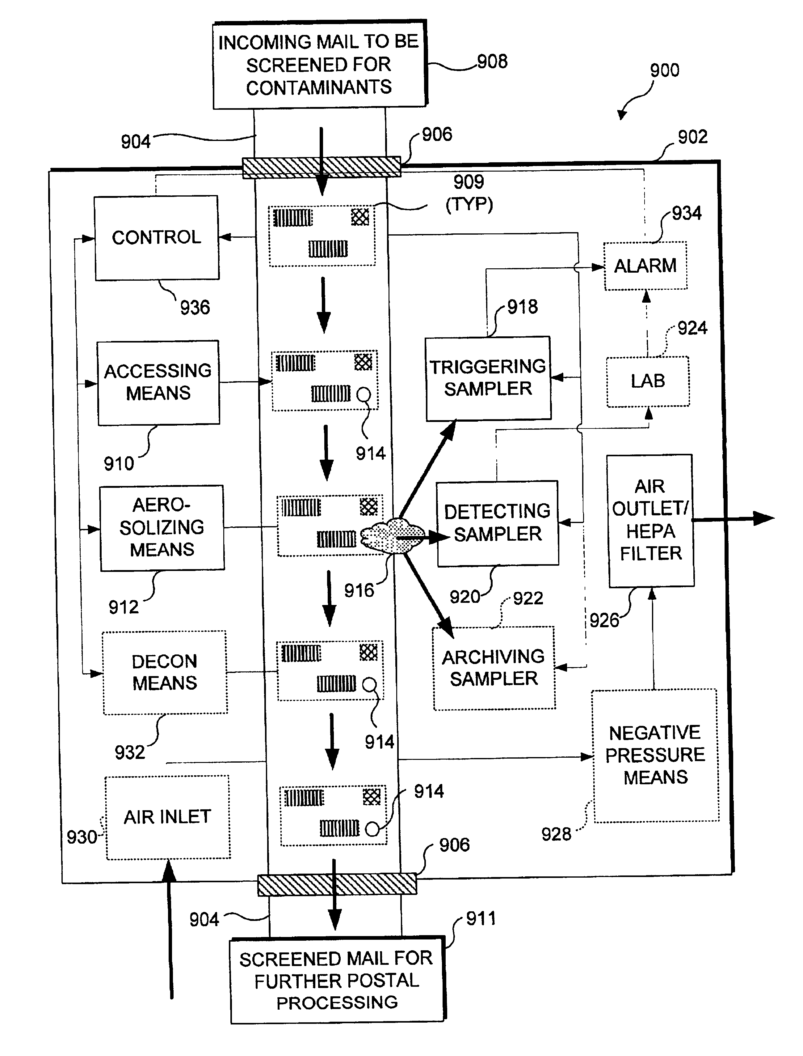
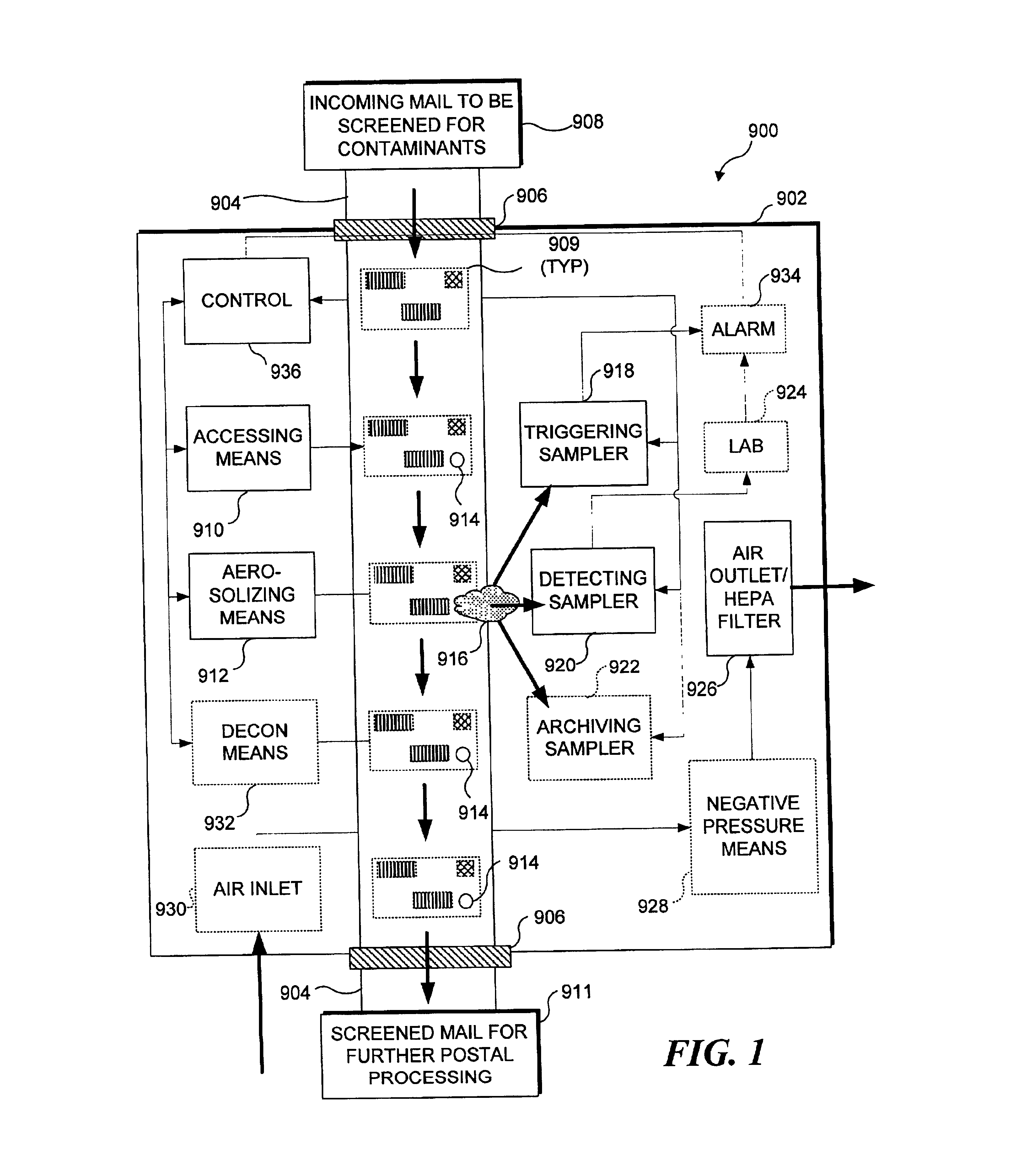
[0093]The present invention relates to a method and apparatus for rapidly analyzing containers to determine if such containers are contaminated with chemical or biological agents.

[0094]It should be noted that the preferred embodiments described below are particularly well adapted to screen items of mail for chemical or biological agents. Thus while a preferred embodiment of the invention, described in detail below, refers to screening items of mail, it should be understood that other items can also be screened for chemical or biological agents using the present invention. For examples, private delivery companies specializing in delivering packages more rapidly than the USPS could use the principles of the present invention to screen packages they accept for delivery. Similarly, freight companies that transport packaged goods over the road may also employ the concepts described herein to screen packages they accept for delivery. Clearly, the principles of the present inventio...


PUM

PropertyMeasurementUnit
Wavelengthaaaaaaaaaa
Pressureaaaaaaaaaa

Abstract

Items of mail are rapidly processed in a mail sampling system to determine if the mail is contaminated with a chemical or biological agent. The mail sampling system maintains a negative pressure in a containment chamber and includes a triggering sampler that makes a threshold determination regarding possible contamination, and a detecting sampler that obtains a sample for more detailed analysis in response to a signal from the triggering sampler. A sample of particulates collected from an item of mail is either removed for analysis or analyzed in the system to identify a contaminating agent. Optionally, the system includes an archiving sampler, which archives samples for subsequent processing and analysis, and a decontamination system, which is activated to decontaminate the mail if needed.

Description

RELATED APPLICATIONS[0001]This application is based on prior copending U.S. Provisional Patent Application Ser. No. 60 / 337,674, filed on Nov. 13, 2001, the benefit of the filing date of which is hereby claimed under 35 U.S.C. § 119(e). The present application is a continuation-in-part of prior U.S. patent application Ser. No. 09 / 775,872, filed on Feb. 1, 2001, now U.S. Pat. No. 6,729,196, which itself is a continuation-in-part of U.S. Pat. No. 6,267,016, and of prior U.S. patent application Ser. No. 09 / 265,620, both filed on Mar. 10, 1999, now U.S. Pat. No. 6,363,800, the benefit of the filing dates of which are hereby claimed under 35 U.S.C. § 120. Further, the present application is a continuation-in-part of prior U.S. patent application Ser. No. 09 / 955,481, filed on Sep. 17, 2001, now U.S. Pat. No. 6,695,146, which itself is a continuation-in-part of Ser. No. 09 / 191,980, now U.S. Pat. No. 6,062,392 (filed on Nov. 13, 1998) and Ser. No. 09 / 494,962, now U.S. Pat. No. 6,290,065 (fil...

Claims


Application Information

Patent Timeline
IPC IPC(8): B01D45/00B01D45/08B01D21/24G01N1/34G01N1/22G01N15/02G01N1/02G01N15/00G01N1/24G01N1/40G01N35/00B01L3/00
CPCB01D21/2455G01N1/2273G01N1/34B01D45/08Y10T436/163333B01L3/5027G01N1/2208G01N1/24G01N1/40G01N35/00009G01N2001/022G01N2001/025G01N2001/2276G01N2015/0026G01N2015/0046G01N2015/0088G01N2015/0288Y10T436/173076Y10T436/17Y10T436/118339Y10T436/25
Inventor CALL, CHARLES J.HANCZYC, ERICKAMHOLZ, ANDREW
Owner FLIR DETECTION
Why Eureka
Try Eureka