Linac for ion beam acceleration

a linear accelerator and ion beam technology, applied in linear accelerators, basic electric elements, electric instruments, etc., can solve the problems of unpractical existing accelerators, less suited conventional cyclotrons, and low cost of early accelerators, and achieve the effect of reducing the overall dimensions of accelerators and being easy to install

Inactive Publication Date: 2005-05-03
FOND PER ADROTERAPIA ONCOLOGICA TERA
View PDF9 Cites 32 Cited by
  • Summary
  • Abstract
  • Description
  • Claims
  • Application Information

AI Technical Summary

Benefits of technology

[0031]Accordingly, the main object of the present invention is to provide a new ion beam accelerator, a system containing such an accelerator and also a method for accelerating ion beams able to satisfy the above-mentioned requirements. Another object of the present invention is to use some new as well as some ex

Problems solved by technology

Early accelerators' cost and size practically limited the utilisation thereof to research laboratories.
Even today, the existing accelerators are often unpractical for many applications making use of ions.
If the request is for ion beams of large mass-over-charge ratio and/or for the velocity range up to about 0.6 times that of light, conventional cyclotrons are less suited.
If a large range has to be covered, different linac structures, each optimally chosen in its frequency range, are serially disposed, with a consequent increased complexity and cost of the whole system.
Some power is d

Method used


Image

  • Linac for ion beam acceleration
  • Linac for ion beam acceleration
  • Linac for ion beam acceleration

Examples


Embodiment Construction

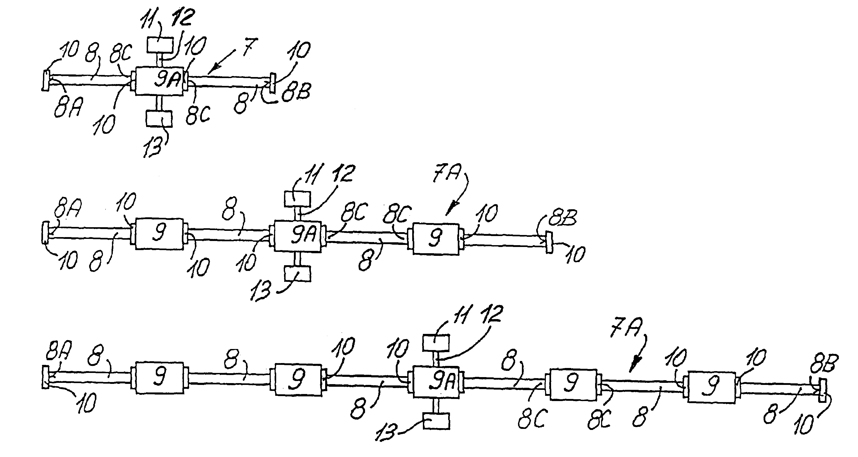
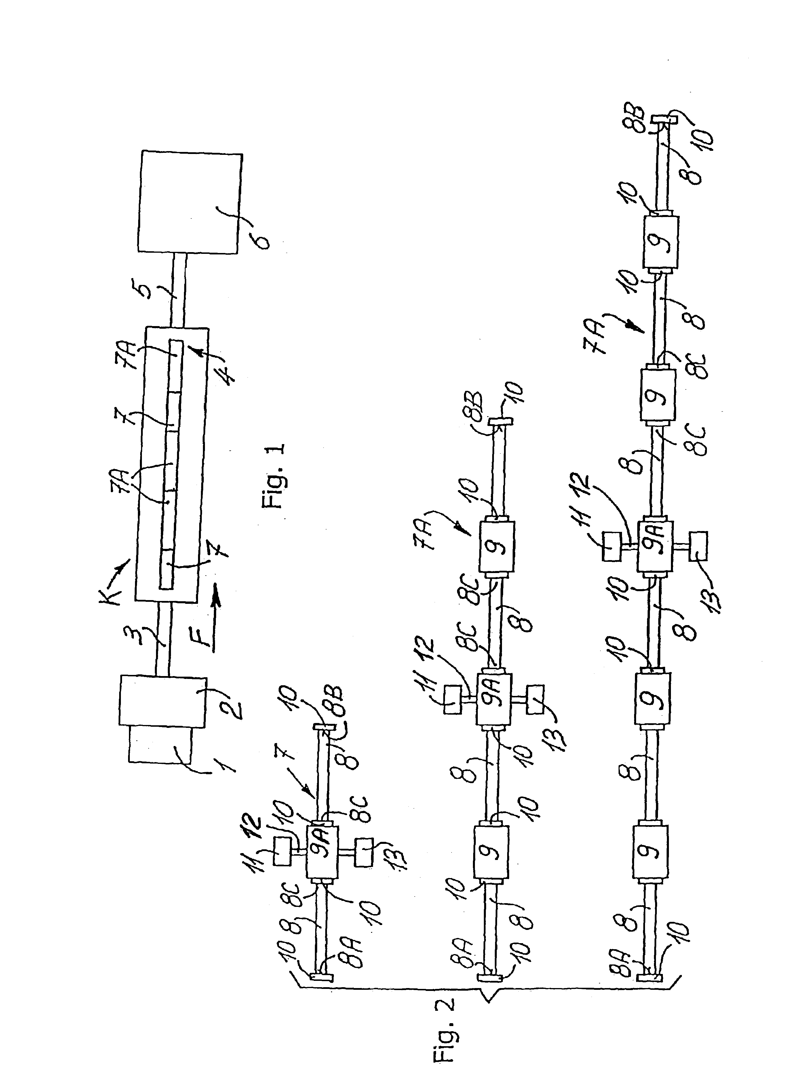
[0050]In the different figures, the same reference number always refers to the same element. Only the parts necessary for the comprehension of the invention have been illustrated. In the following structural, functional and method description, we refer firstly to FIG. 1, which shows a block diagram of a system or a complete complex K comprising a linac developed according to the present invention and indicated as a whole with 4.

[0051]A conventional ion source 1 injects a collimated ion beam into a conventional “injector”2, for instance an electrostatic accelerator, or a small cyclotron, or an RFQ. The arrow F indicates the beam direction. The pre-accelerated beam is then injected into a conventional low energy beam transport section (LEBT) 3, which focuses and steers the beam up to the entry of the accelerator or linac 4 according to the invention. Said linac 4 is a kind of Drift Tube Linac (DTL), working at high frequency, for instance for cancer therapy applications. Said linac 4 ...


PUM


Abstract

A drift tube linear accelerator (linac) that can be used for the acceleration of low energy ion beams. The particles enter the linac at low energy and are accelerated and focused along a straight line in a plurality of resonant accelerating structures interposed by coupling structures up to the desired energy. In the accelerating structures, excited by an H-type resonant electromagnetic field, a plurality of accelerating gaps is provided between drift tubes supported by stems, for instance alternatively horizontally and vertically disposed. A basic module composed of two accelerating structures and an interposed coupling structure, or a modified coupling structure connected to a RF power generator, is if necessary linked to a vacuum system and equipped with one or more quadrupoles.

Description

FIELD OF THE INVENTION[0001]The present invention relates to a drift tube linear accelerator (linac) for accelerating ions as a beam, a system comprising such a linac and a method for accelerating an ion beam according to the preambles of claims 1, 8 and 11, respectively. The invention also relates to the application fields of the disclosed linac, system and accelerating method.BACKGROUND OF THE INVENTION[0002]It is well known that particle accelerators are used to accelerate ions (protons and heavier ions) to very high velocities. At high velocities, a large number of such particles form what is called a “beam”, and this beam can be used for different purposes, for instance research, medical or industrial applications. Early accelerators' cost and size practically limited the utilisation thereof to research laboratories. Even today, the existing accelerators are often unpractical for many applications making use of ions.[0003]Existing accelerators are of three kinds: cyclotrons, li...

Claims


Application Information

Patent Timeline
IPC IPC(8): H05H7/22H05H7/00H05H9/00
CPCH05H9/00H05H7/22
Inventor AMALDI, UGOCRESCENTI, MASSIMOZENNARO, RICCARDO
Owner FOND PER ADROTERAPIA ONCOLOGICA TERA
Why Eureka
Try Eureka