Flex-circuit-based high speed transmission line

a high-speed transmission line and flex circuit technology, applied in the direction of high-frequency circuit adaptation, waveguide, dielectric characteristics, etc., can solve the problems of unacceptably high dc resistance, low maximum bandwidth of conventional flex circuits, and significant limitations of such transmission line circuits relating to the nature of dielectric materials, etc., to achieve the effect of greater performance and low average dielectric constan

Inactive Publication Date: 2005-05-03
XANDEX
View PDF10 Cites 67 Cited by
  • Summary
  • Abstract
  • Description
  • Claims
  • Application Information

AI Technical Summary

Benefits of technology

[0007]According to the present invention, transmission line circuits are provided in which an intervening structure or layer is interposed between signal traces and a conductive plane and maintains a substantially constant separation between the traces and the conductive plane. At least a portion of the intervening layer or structure is air (Er=1.0), resulting in a very low average dielectric constant which is experienced by the transmission lines. This, in turn, allows for the construction of a transmission line circuit with much greater performance than conventional constructions.

Problems solved by technology

Significant limitations associated with such transmission line circuits relate to the nature of the dielectric material.
As a result, conventional flex circuits have low maximum bandwidth (e.g., −3 dB @ 3 GHz for 2-inch long traces), and unacceptably high DC resistance due to the narrow trace widths possible with conventional dielectric materials.
In addition, if the thickness of these dielectric materials is to be kept within a range appropriate for most applications, only very narrow traces are possible if the transmission lines are to remain within the typical 50 ohm transmission line design rules.
Due to their width and high resistance, these narrow traces result in transmission lines with low current carrying capacity.
However, these constructions have been reported to be very fragile and expensive.

Method used


Image

  • Flex-circuit-based high speed transmission line
  • Flex-circuit-based high speed transmission line
  • Flex-circuit-based high speed transmission line

Examples


Embodiment Construction

[0018]Reference will now be made in detail to specific embodiments of the invention including the best modes contemplated by the inventors for carrying out the invention. Examples of these specific embodiments are illustrated in the accompanying drawings. While the invention is described in conjunction with these specific embodiments, it will be understood that it is not intended to limit the invention to the described embodiments. On the contrary, it is intended to cover alternatives, modifications, and equivalents as may be included within the spirit and scope of the invention as defined by the appended claims. In the following description, numerous specific details are set forth in order to provide a thorough understanding of the present invention. The present invention may be practiced without some or all of these specific details. In addition, well known process operations have not been described in detail in order not to unnecessarily obscure the present invention.
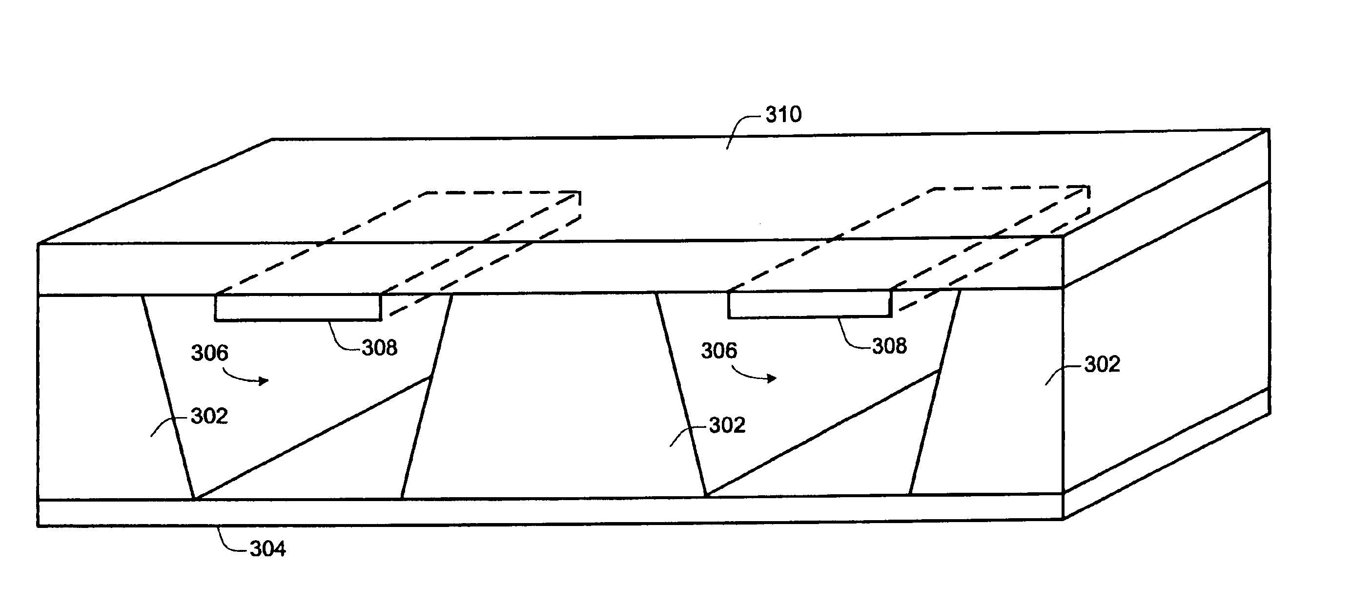
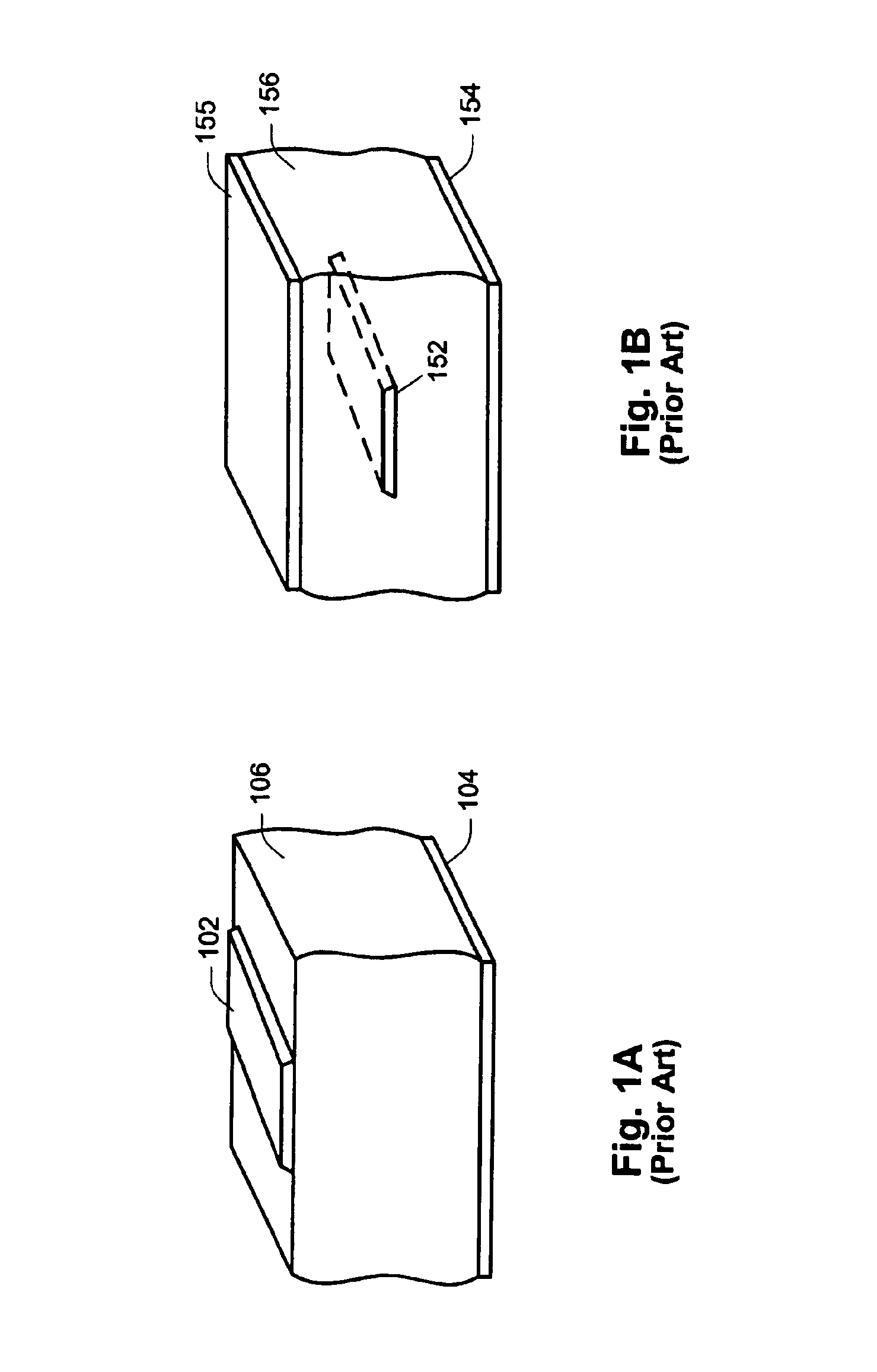
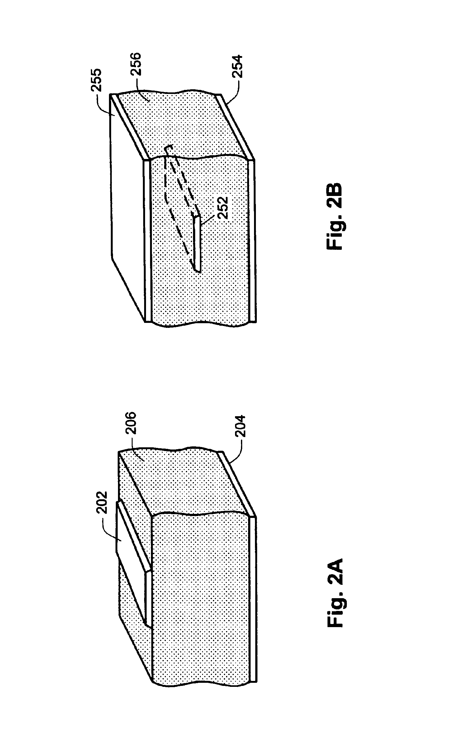
[0019]As dis...


PUM

PropertyMeasurementUnit
degree anglesaaaaaaaaaa
impedanceaaaaaaaaaa
angleaaaaaaaaaa

Abstract

A transmission line circuit is described which includes a conductive plane, a plurality of signal traces, and an intermediate layer between the conductive plane and the signal traces. The intermediate layer maintains a substantially constant separation between the conductive plane and the signal traces. At least a portion of the intermediate layer comprises air. The signal traces and the conductive plane form transmission lines.

Description

RELATED APPLICATION DATA[0001]The present application claims priority from U.S. Provisional Patent Application No. 60 / 440,074 for FLEX-CIRCUIT-BASED HIGH SPEED TRANSMISSION LINE filed on Jan. 13, 2003, the entire disclosure of which is incorporated herein by reference for all purposes.BACKGROUND OF THE INVENTION[0002]The present invention relates to high speed transmission lines and, more specifically, to transmission line circuits employing flex circuits.[0003]Conventional transmission line flex circuits typically employ one of two configurations, a microstrip construction shown in FIG. 1A and a stripline construction shown in FIG. 1B. In the microstrip (i.e., single-sided) construction, a signal trace 102 is separated on one side from a ground plane 104 by an intervening dielectric 106. In the stripline (i.e., double-sided) construction a signal trace 152 is separated on both sides from ground planes 154 and 155 by surrounding dielectric 156.[0004]Significant limitations associate...

Claims


Application Information

Patent Timeline
Patent Type & Authority Patents(United States)
IPC IPC(8): H01P3/08H05K1/02H05K1/00
CPCH01P3/081H01P3/084H05K1/024H05K2201/2036H05K2201/0116H05K2201/0715H05K2201/09672H05K1/0393
Inventor SINSHEIMER, ROGERTEMER, VLADAN
Owner XANDEX
Why Eureka
Try Eureka