Lens for image pickup

Inactive Publication Date: 2005-05-03
MILESTONE CO LTD +1
View PDF29 Cites 11 Cited by
  • Summary
  • Abstract
  • Description
  • Claims
  • Application Information

AI Technical Summary

Benefits of technology

[0029]By employing a lens configuration which satisfies the five conditions of the above-described condition equations (1) through (5), a lens fo

Problems solved by technology

However, such lens systems employ lenses which are expensive due to the use of aspherical molded glass, or in which the curvature radius cannot, due to machining constraints, be made small in order to shorten the optical length.
Lens systems are also seen in which a single lens is used, in order to achieve a short optical length, so that cons

Method used


Image

  • Lens for image pickup
  • Lens for image pickup
  • Lens for image pickup

Examples


first embodiment

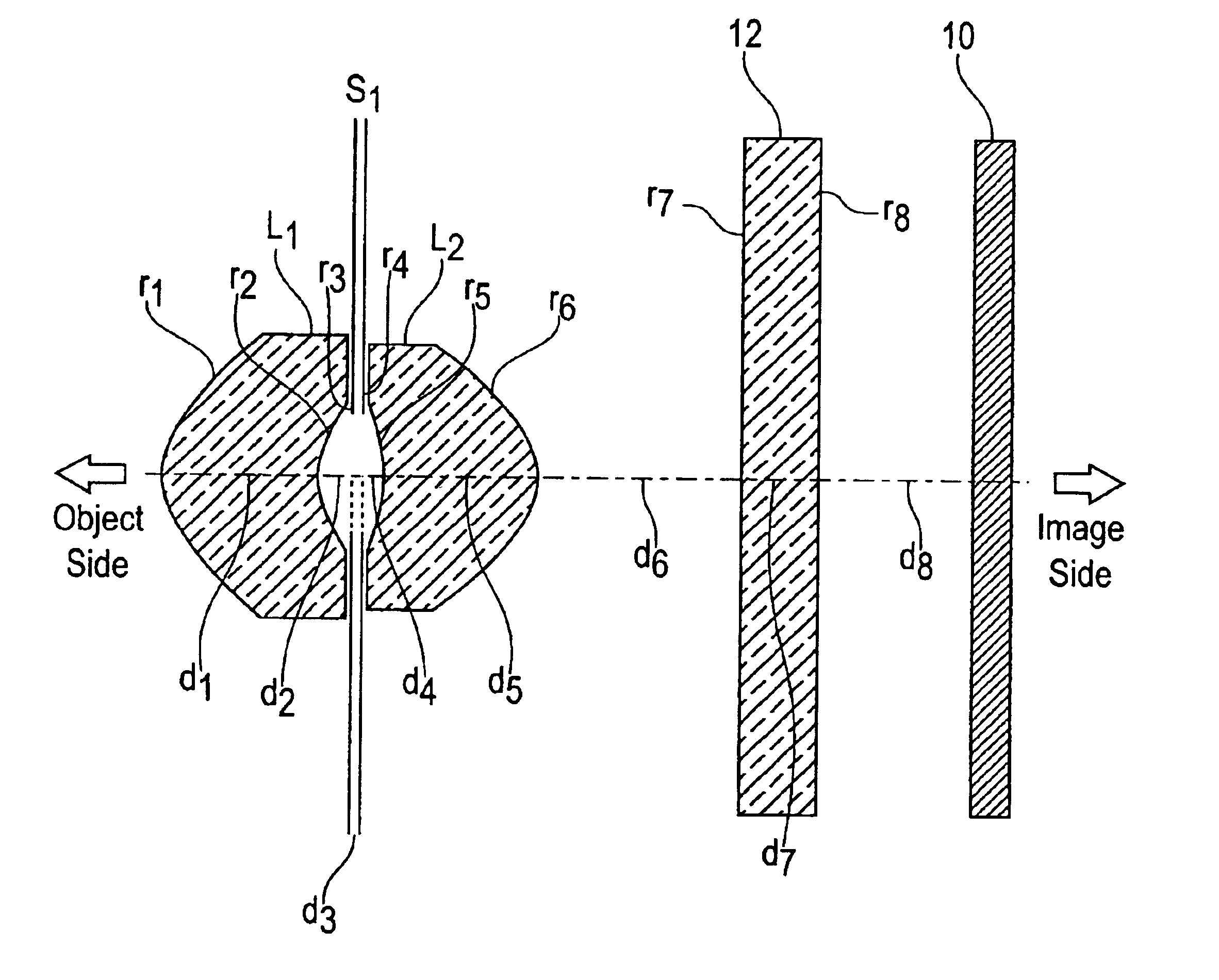
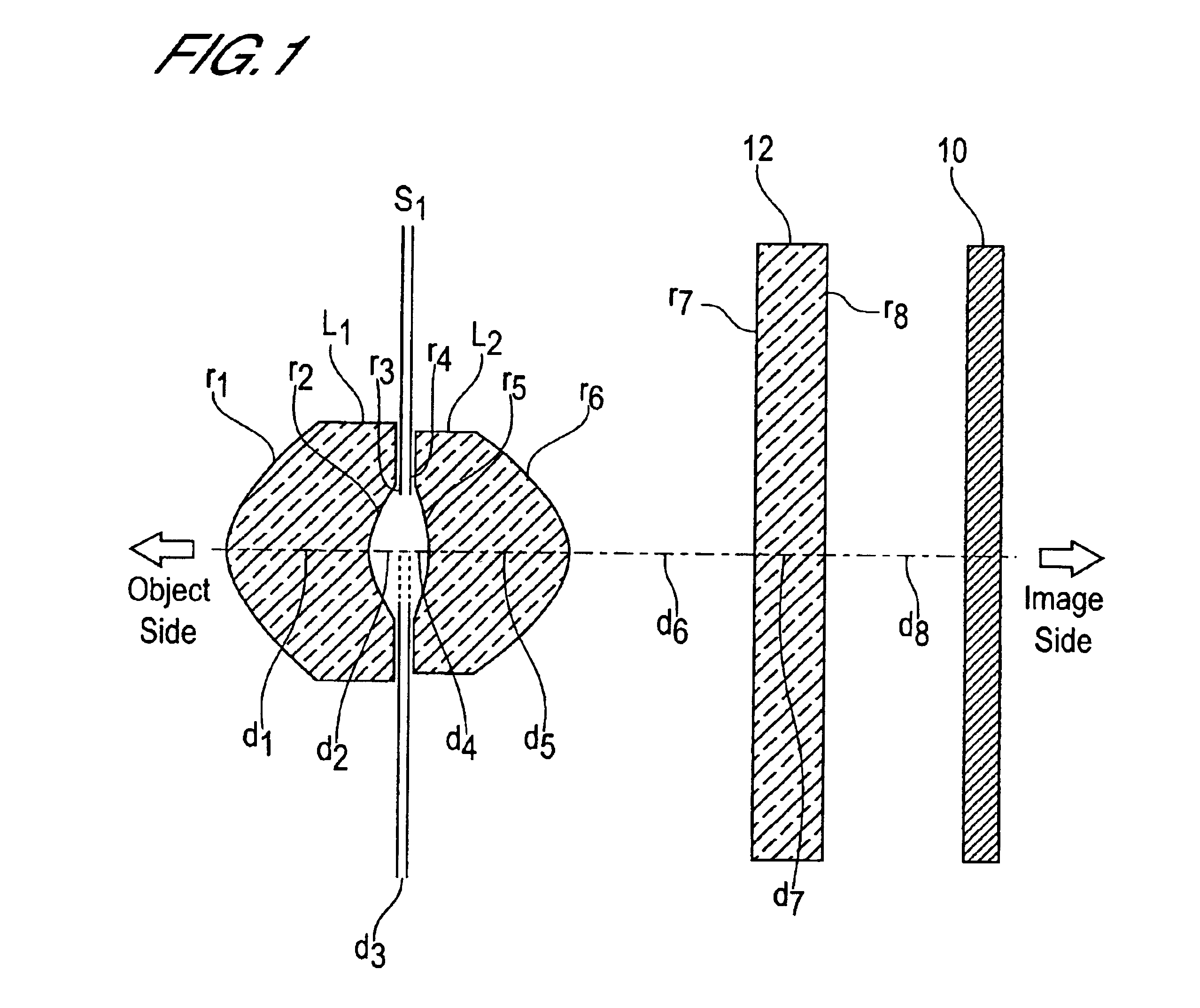
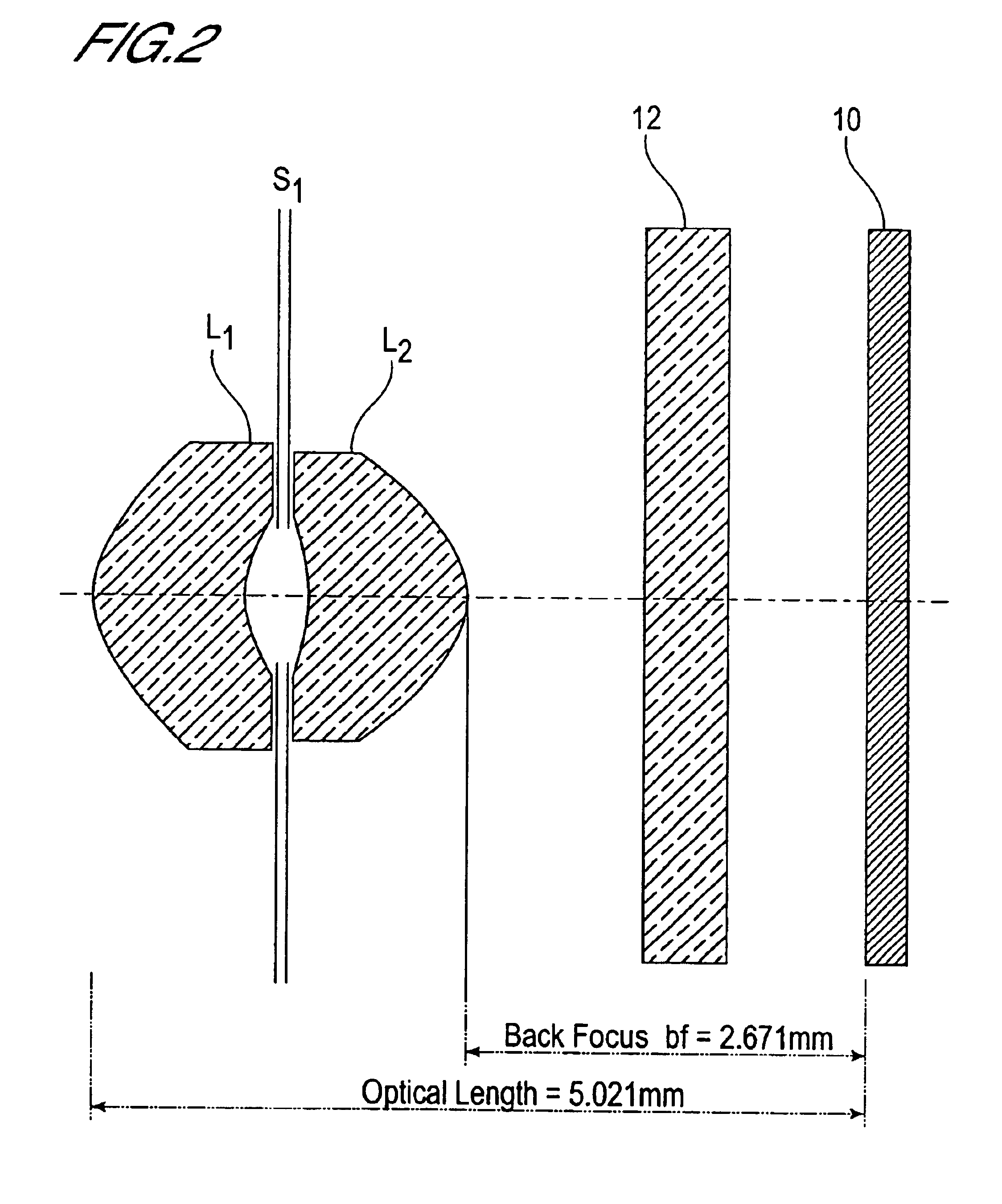
[0085[0086](A) The focal length f of the entire lens is f=3.718 mm.[0087](B) The object-side curvature radius r5 of the second lens L2 is r5=−1.5132 mm.[0088](C) The image-side curvature radius r6 of the second lens L2 is r6=−0.9973 mm.[0089](D) The back focus bf is bf=2.671 mm.[0090](E) The distance in air from the object-side surface of the first lens L1 to the image plane, that is, the optical length d, is d=5.021 mm.[0091](F) The object-side curvature radius r1 of the first lens L1 is r1=1.1005 mm.[0092](G) The image-side curvature radius r2 of the first lens L1 is r2=0.9969 mm.[0093](H) The interval D2 between the first lens L1 and the second lens L2 is D2=0.35 mm.[0094](I) The focal length f1 of the first lens L1 is f1=8.68 mm.[0095](J) The focal length f2 of the second lens L2 is f2=3.34 mm.

[0096]Hence the following obtain:[0097](1) |r5 / f|=|−1.5132 / 3.718|=0.407,[0098](2) (r5 +r6) / (r5−r6)=(1.5132+0.9973) / (1.5132−0.9973)=4.866,[0099](3) d / f=5.021 / 3.718=1.350,[0100](4) r1 / r2=1.1...

second embodiment

[0111[0112](A) The focal length f of the entire lens is f=3.800 mm.[0113](B) The object-side curvature radius r5 of the second lens L2 is r5=−1.760 mm.[0114](C) The image-side curvature radius r6 of the second lens L2 is r6=−1.486 mm.[0115](D) The back focus bf is bf=1.831 mm.[0116](E) The distance in air from the object-side surface of the first lens L1 to the image plane, that is, the optical length d, is d=4.231 mm.[0117](F) The object-side curvature radius r1 of the first lens L1 is r1=1.020 mm.[0118](G) The image-side curvature radius r2 of the first lens L1 is r2=1.266 mm.[0119](H) The interval D2 between the first lens L1 and the second lens L2 is D2=0.35 mm.[0120](I) The focal length f1 of the first lens L1 is f1=3.94 mm.[0121](J) The focal length f2 of the second lens L2 is f2=8.29 mm.

[0122]Hence the following obtain:[0123](1) |r5 / f|=|−1.760 / 3.800|=0.463,[0124](2) (r5+r6) / (r5−r6)=(1.760+1.486) / (1.760−1.486)=11.85,[0125](3) d / f=4.231 / 3.800=1.1134,[0126](4) r1 / r2=1.020 / 1.266=...

third embodiment

[0135[0136](A) The focal length f of the entire lens is f=3.302 mm.[0137](B) The object-side curvature radius r5 of the second lens L2 is r5=−1.976 mm.[0138](C) The image-side curvature radius r6 of the second lens L2 is r6=−1.154 mm.[0139](D) The back focus bf is bf=1.795 mm.[0140](E) The distance in air from the object-side surface of the first lens L1 to the image plane, that is, the optical length d, is d=4.145 mm.[0141](F) The object-side curvature radius r1 of the first lens L1 is r1=1.0546 mm.[0142](G) The image-side curvature radius r2 of the first lens L1 is r2=1.1658 mm.[0143](H) The interval D2 between the first lens L1 and the second lens L2 is D2=0.30 mm.[0144](I) The focal length f1 of the first lens L1 is f1=4.78 mm.[0145](J) The focal length f2 of the second lens L2 is f2=3.78 mm.

[0146]Hence the following obtain:[0147](1) |r5 / f|=|−1.976 / 3.3021=0.598,[0148](2) (r5+r6) / (r5−r6)=(1.976+1.154) / (1.976−1.154)=3.808,[0149](3) d / f=4.145 / 3.302=1.2553,[0150](4) r1 / r2=1.0546 / 1.1...


PUM


Abstract

A lens for image pickup is provided in which various aberrations are corrected satisfactorily, the optical length is at maximum approximately 6 mm, and moreover a sufficient back focus is secured. This lens for image pickup comprises a first lens, an aperture diaphragm, and a second lens, positioned in this order from the object side toward the image side. The first lens is a resin lens with a meniscus shape, with the convex surface facing the object side, and having positive refractive power. The second lens is a resin lens with a meniscus shape, with the convex surface facing the image side, and having positive refractive power.

Description

BACKGROUND OF THE INVENTION[0001]1. Field of the Invention[0002]This invention relates to a lens for image pickup, and in particular to a lens for image pickup suitable for application in image input devices for portable telephones and personal computers, digital cameras, CCD cameras for monitoring, inspection equipment, and other equipment employing a CCD or CMOS as an imaging device.[0003]2. Description of Related Art[0004]A lens for image pickup as described above must have a short optical length, defined as distance from the incidence plane on the object side of the lens for image pickup to the image pickup surface (the image-formation surface of the CCD or similar). Taking a portable telephone as an example, the optical length must be shorter than, at least, the thickness of the portable telephone set. On the other hand, it is preferable that the back focus, defined as the distance from the emission plane on the image side of the lens for image pickup to the image pickup surfac...

Claims


Application Information

Patent Timeline
IPC IPC(8): G02B13/18G02B13/00G02B3/04G02B3/02G02B9/08G02B9/00G03B30/00
CPCG02B3/04G02B13/18G02B13/003G02B9/08G03B9/02G02B1/041
Inventor DO
Owner MILESTONE CO LTD
Why Eureka
Try Eureka