Automatic test system for an analog micromirror device

a micromirror and automatic testing technology, applied in the direction of testing circuits, instruments, optical elements, etc., can solve the problems of time-consuming procedures, inability to use physical cables for transmitting light signals, and the inability to perform the necessary tests manually on a single analog micromirror device, etc., to achieve the effect of reducing the time it takes to perform the necessary tests

Inactive Publication Date: 2005-05-03
TEXAS INSTR INC
View PDF4 Cites 8 Cited by
  • Summary
  • Abstract
  • Description
  • Claims
  • Application Information

AI Technical Summary

Benefits of technology

[0010]Another aspect of the invention includes a method of testing a micromirror device comprising activating a light source to generate a light beam which impinges on a mirror surface of the micromirror device to produce a reflected beam which impinges on a position sensitive device. A voltage signal is applied to a current driver for generating a current signal through coils for moving ...

Problems solved by technology

As opposed to fiber optic-based optical communications, however, this approach does not use a physical cable for transmission of the light signal.
Currently these dev...

Method used


Image

  • Automatic test system for an analog micromirror device
  • Automatic test system for an analog micromirror device
  • Automatic test system for an analog micromirror device

Examples


Embodiment Construction

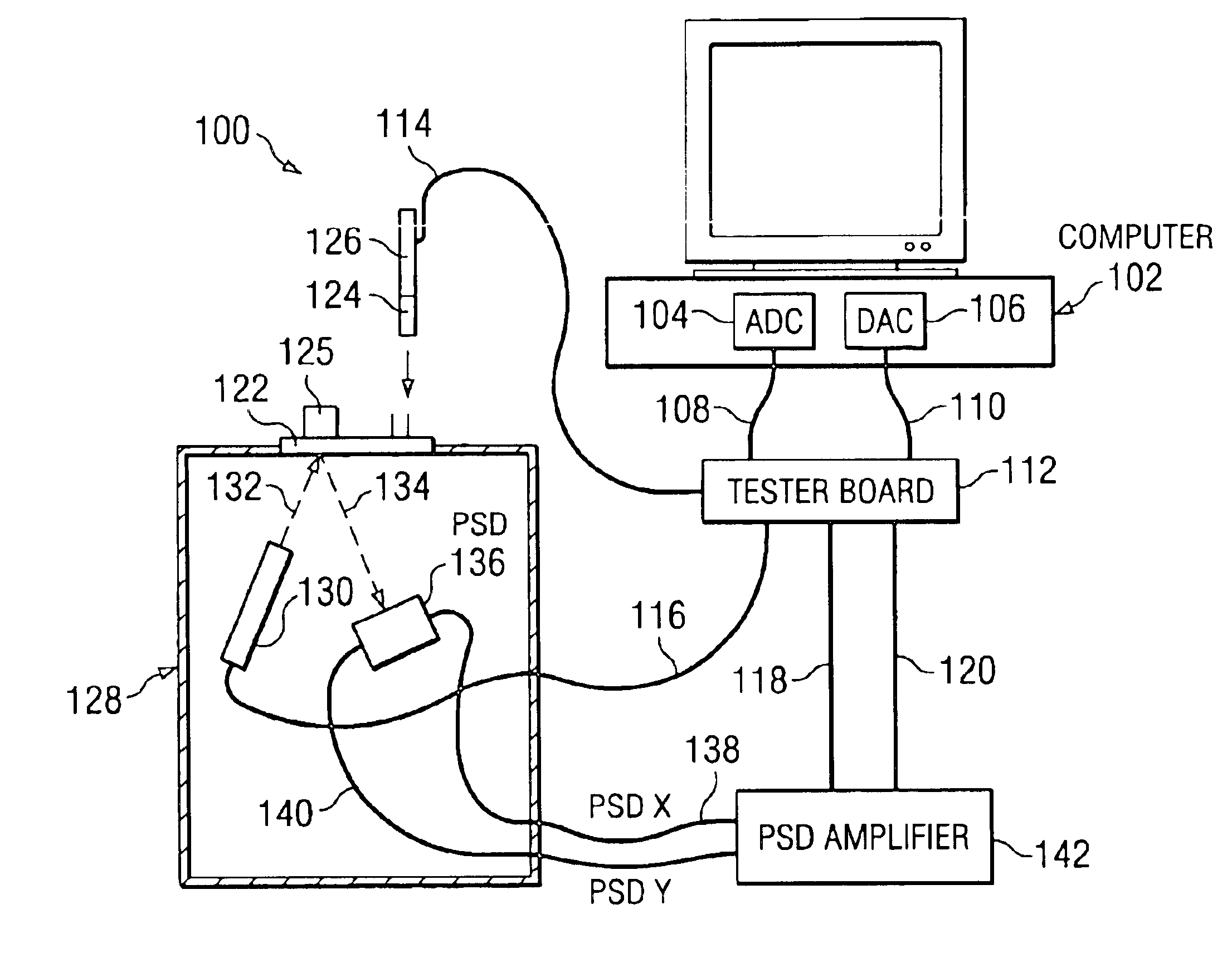
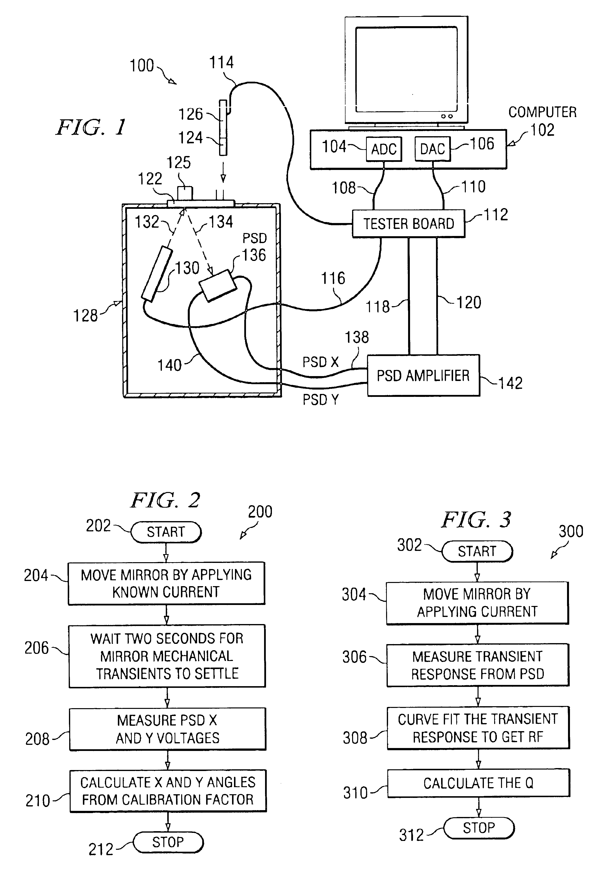
[0018]FIG. 1 shows a block diagram of an automatic test system for an analog micromirror device according to the present invention generally as 100. The system comprises a computer 102 which may be a personal computer, for example. The computer has an analog to digital converter card 104 and digital to analog converter card 106 connected to the peripheral bus thereof. For example, the cards can be PCI cards made by National Instruments. The analog to digital converter card 104 is connected to a tester board 112 via cable 108 and the digital to analog converter card 106 is connected to the tester board 112 via cable 110. The micromirror device 125 is attached to a “black box”128 via a mounting 122. The mounting 122 is designed to hold the micromirror device to the black box 128 so that the connector portion faces towards the top of the box and the micromirror device is exposed to the inside of the box via a hole in the mounting 122. The “black box”128 is in the preferred embodiment l...


PUM


Abstract

An automatic tester for an analog micromirror device includes a computer having an ADC and DAC connected to its peripheral bus. A micromirror device under test is mounted on a black box containing a light source such as a laser and a position sensitive device. The light beam is reflected by the micromirror device onto the position sensitive device so that the deflection of the mirror in two axes can be measured. The output of the position sensitive device is amplified and coupled to the ADC via a tester board. The computer can test the micromirror device to detect mechanical failure and to measure the resonant frequency and Q of the driving coils, and SNR of the internal package feedback which measures the position of the mirror.

Description

REFERENCE TO RELATED APPLICATION[0001]This application is related to U.S. patent application Ser. No. 10 / 318,684 (TI-34743) entitled “Current Driver for an Analog Micromirror Device”, commonly assigned and filed on even date herewith, which is incorporated herein by reference.FIELD OF THE INVENTION[0002]This application relates to testing a micromirror device, and more particularly to a current driver utilized in an automatic test system for an analog micromirror device.BACKGROUND OF THE INVENTION[0003]Modern data communications technologies have greatly expanded the ability to communicate large amounts of data over many types of communications facilities. This explosion in communications capability not only permits the communications of large databases, but has also enabled the digital communications of audio and video content. This high bandwidth communication is now carried out over a variety of facilities, including telephone lines (fiber optic as well as twisted-pair), coaxial ...

Claims


Application Information

Patent Timeline
IPC IPC(8): G06F19/00G02B26/08
CPCG02B26/0833
Inventor PILLAI, NARAYANA SATEESH
Owner TEXAS INSTR INC
Why Eureka
Try Eureka