Position measuring device using change in inductance of coil, float-type flowmeter, and position measuring method

a technology of inductance change and measurement device, which is applied in the direction of liquid/fluent solid measurement, volume/mass flow by dynamic fluid flow effect, instruments, etc., can solve the problems of high cost of using this kind of length measuring unit, complex structure of proportional variable differential transformer, and inability to measure a desired flow rate. , to achieve the effect of low cost and simple structur

Inactive Publication Date: 2005-05-10
SMC CORP
View PDF11 Cites 25 Cited by
  • Summary
  • Abstract
  • Description
  • Claims
  • Application Information

AI Technical Summary

Benefits of technology

[0009]It is therefore an object of the present invention to provide a position measuring device which is simple in structur

Problems solved by technology

The disclosed float-type flowmeter, however, is unable to measure a desired flow rate unless the float has a length greater than the full length of the coils.
Also, the propo

Method used


Image

  • Position measuring device using change in inductance of coil, float-type flowmeter, and position measuring method
  • Position measuring device using change in inductance of coil, float-type flowmeter, and position measuring method
  • Position measuring device using change in inductance of coil, float-type flowmeter, and position measuring method

Examples


Embodiment Construction

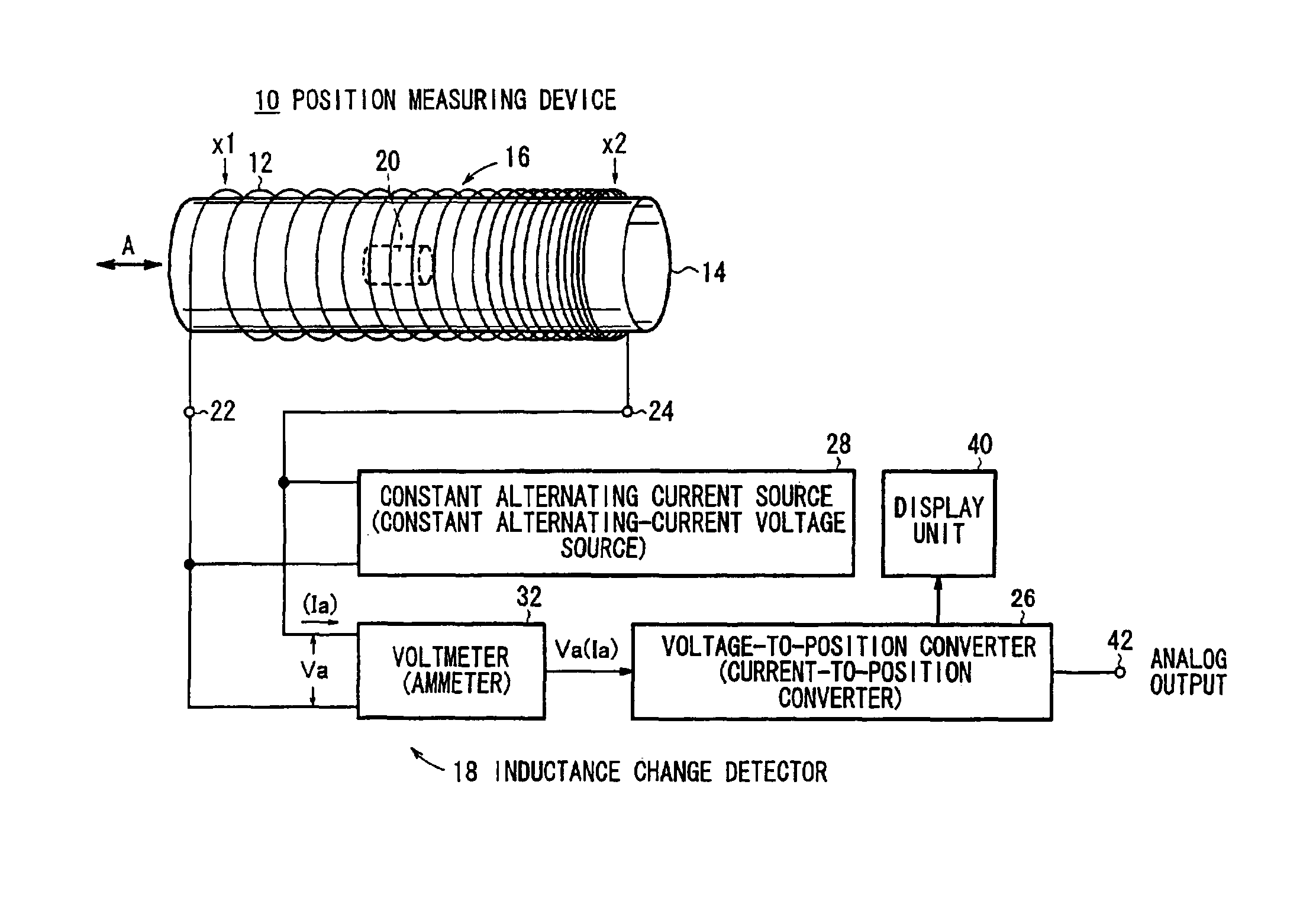
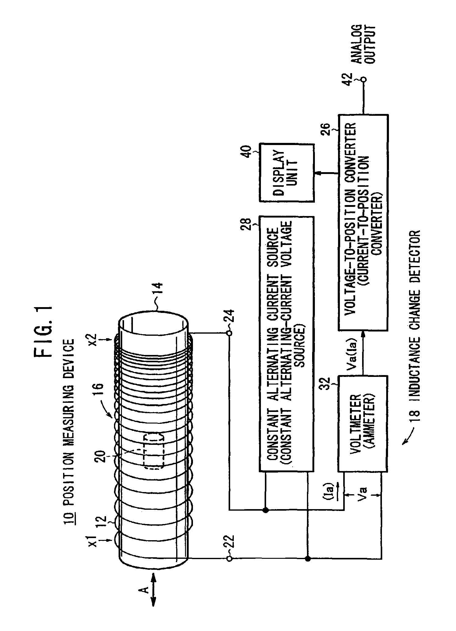
[0049]FIG. 1 is illustrative of the principles of a position measuring device 10 according to an embodiment of the present invention.

[0050]The position measuring device 10 has a cylindrical coil 16 which is a conductor 12 wound around a hollow rod 14 as a bobbin. The coil 16 is wound such that the density of magnetic fluxes produced by the conductor 12 differs gradually along an axial direction A of the coil 16 when the conductor 12 is supplied with a direct current, i.e., when the conductor 12 is excited by a direct current or by an alternating current.

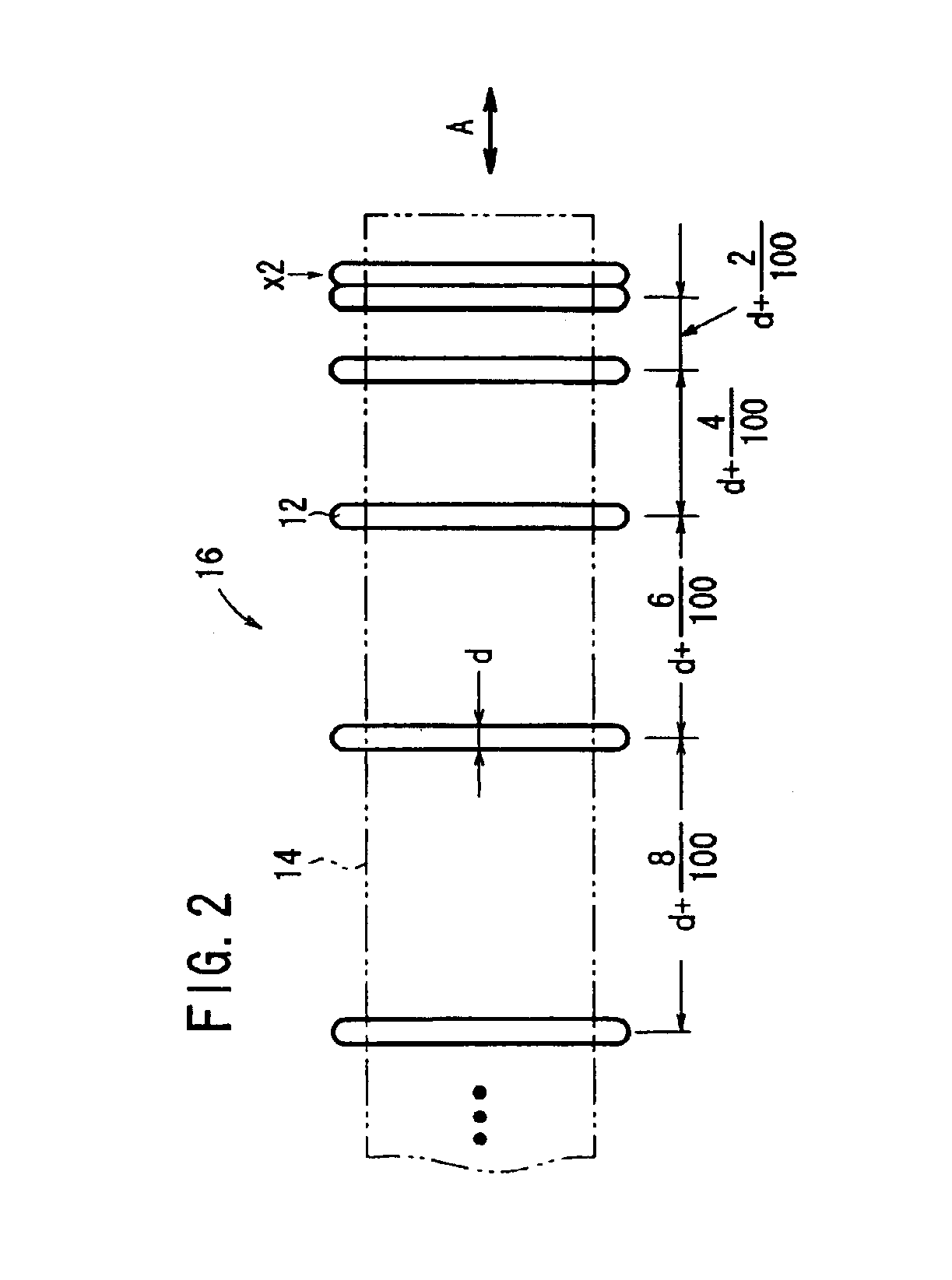
[0051]The coil 16 has terminals 22, 24 on the respective opposite ends of the conductor 12. The cross-sectional shape of the coil 16 perpendicular to the axial direction A, are circular with a constant area. The conductor 12 is wound at intervals which are gradually smaller from a position x1 at one end of the conductor 12 toward a position x2 at the other end. The coil 16 is not limited to the circular cross-sectional shape shown in...


PUM


Abstract

A float-type flowmeter measures the rate of a fluid flowing upwardly through a tube based on the position of a float movably disposed in the tube and including a magnetic material. A coil is wound around the tube such that the intervals gradually decrease in an axial direction. The coil is excited by an alternating current supplied from an inductance change detector. The inductance change detector detects a change in the inductance of the coil which is caused when the float moves in the axial direction, and generates a voltage. A voltage-to-position (flow rate) converter determines a flow rate from the voltage corresponding to the position of the float.

Description

BACKGROUND OF THE INVENTION[0001]1. Field of the Invention[0002]The present invention relates to a position measuring device for measuring a position using a change in the inductance of a coil, which is suitable as a microflowmeter which is capable of measuring a flow rate in, for example, the range from 10 to 100 [ml / min.], or a length measuring unit for measuring a length of a piston rod as it is displaced into or out of a sleeve, a float-type flowmeter, and a position measuring method.[0003]2. Description of the Related Art[0004]There has been a demand in the market for a float-type flowmeter which is capable of electrically, instead of visually, detecting the position of a float in a fluid. This float-type flowmeter is needed in applications where the float position cannot be visually recognized when the fluid is deeply colored, or when the float position is detected for automatically controlling the rate of the fluid.[0005]One conventional float-type flowmeter for electrically ...

Claims


Application Information

Patent Timeline
IPC IPC(8): G01F1/20G01F1/24G01B7/00G01D5/20
CPCG01F1/24G01F23/38
Inventor TOMITA, SEIJIKAWASAKI, SETSUROSOTOME, MOTOHIROWATANABE, TSUYOSHI
Owner SMC CORP
Why Eureka
Try Eureka