Submersible well pumping system with improved flow switching mechanism

Inactive Publication Date: 2005-05-10
SMITH ELEVATOR
View PDF21 Cites 63 Cited by
  • Summary
  • Abstract
  • Description
  • Claims
  • Application Information

AI Technical Summary

Benefits of technology

[0033]For all embodiments disclosed and claimed herein, the auxiliary pump is driven by a prime mover that can be an AC or DC rotary electric motor, an AC or DC linear motor, a hydraulic motor or mechanical actuation from the surface. In the preferred embodiment of the invention, the prime mover is contained in the same housing as the pump, and is powered electrically. The pump may be connected to the motor in such a way that they share a common fluid supply, that is the same fluid is used in the electric motor as is used as the working fluid in the pump. In this arrangement, the fluid input of the auxiliary pump is connected to the electric motor fluid volume. This arrangement has the advantage of reducing the possibility of failure due to working f

Problems solved by technology

The flow switch must completely reverse the flow of working fluid between the working fluid sub-chambers when the pump reaches the end of a stroke, otherwise pump failure will occur.
Because the precise amount of fluid in the working fluid sub-chambers cannot be kno

Method used


Image

  • Submersible well pumping system with improved flow switching mechanism
  • Submersible well pumping system with improved flow switching mechanism
  • Submersible well pumping system with improved flow switching mechanism

Examples


Embodiment Construction

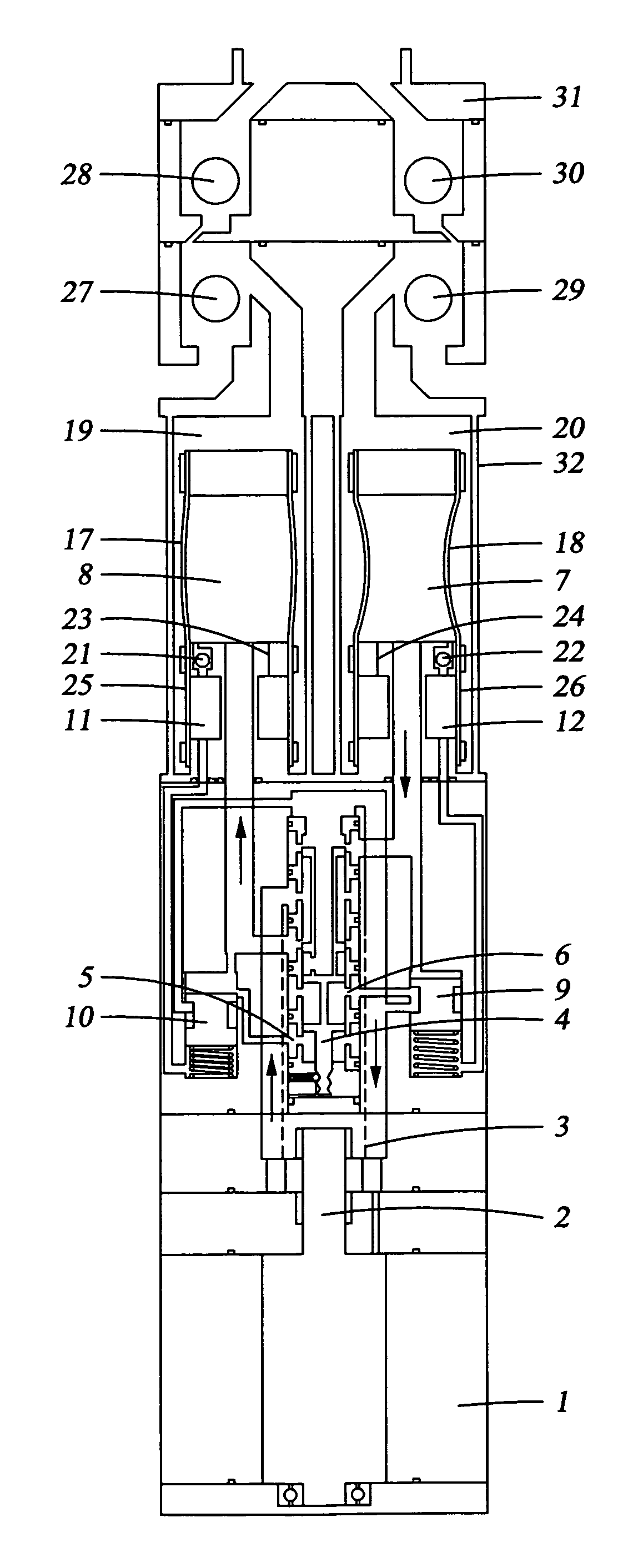
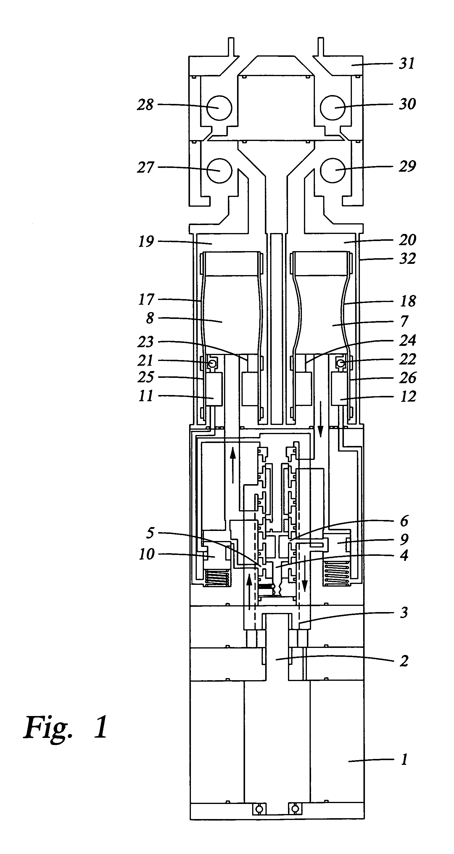
[0040]Referring to FIG. 1, the first preferred embodiment of the diaphragm pump uses a prime mover (1) to supply mechanical energy to operate pump mechanism. The prime mover can be an electric motor, hydraulically actuated motor or mechanically actuated motor. The preferred embodiment uses a Franklin electric “Stripper” series motor that is designed of oil and gas applications. The motor is oil filled, 3-phase, 2-pole, 3450 Synchronous AC. The motor is typically 3¾″ in diameter and several feet long. In the preferred embodiment, any free volume located inside the prime mover is filled with working fluid. The preferred working fluid is 10-weight mineral oil.

[0041]The prime mover attaches to the auxiliary pump with a coupling (2). The coupling transmits torque from the prime mover (1) to the auxiliary pump (3).

[0042]The auxiliary pump (3) produces a flow of working fluid under pressure, converting mechanical rotational energy to hydraulic power. A gear pump is used in the preferred em...


PUM


Abstract

The invention generally concerns a submersible well pumping system comprising an axially elongated housing and a multi-chamber hydraulically driven diaphragm pump suspended in a well. The pump is driven by a self-contained, closed hydraulic system, activated by an electric, pneumatic or hydraulic motor. Several embodiments are used to reverse the flow of working fluid into and out of the working fluid sub-chambers of a two chambered diaphragm pump to operate the diaphragm pump over all operating conditions including starts and stops, and low speed. Generally, the embodiments sense the end of the pumping stroke, either directly or by time. When the end of the pumping stroke is sensed, the direction of flow is reversed by changing the state of a directional valve, operating a reversing clutch, or by deactivating one prime mover-auxiliary pump and activating a second that operates in the reverse direction.

Description

CROSS-REFERENCE TO RELATED APPLICATION[0001]I hereby claim the benefit under Title 35, United States Code Section 119(e) of any United States Provisional Application(s) listed below:[0002]Application No. 60 / 334,484[0003]Filing Date: December 3, 2001.BACKGROUND OF THE INVENTION[0004]1. Technical Field of the Invention[0005]This invention relates generally to submersible well pumping systems. This invention relates particularly to a positive displacement pumping system with an improved, efficient and reliable flow switching mechanism.[0006]2. Description of the Background Art[0007]Hydraulically driven diaphragm pumps are positive displacement pumps that are nearly immune to the effects of sand in the pumped fluid because the pressure generating elements are isolated from the pumped fluid by a flexible diaphragm. In well pump applications, this type of pump is driven by a self contained, closed hydraulic system, activated by an electric or hydraulic motor where the pump, closed hydraul...

Claims


Application Information

Patent Timeline
IPC IPC(8): F04B47/06F04B43/113E21B43/12F04B43/00F04B47/00
CPCE21B43/128F04B47/06F04B43/1136
Inventor TRAYLOR, LELAND B.
Owner SMITH ELEVATOR
Why Eureka
Try Eureka