
Copper electroplating method and apparatus

Inactive Publication Date: 2005-05-10
NOVELLUS SYSTEMS
View PDF58 Cites 106 Cited by
  • Summary
  • Abstract
  • Description
  • Claims
  • Application Information

AI Technical Summary

Benefits of technology

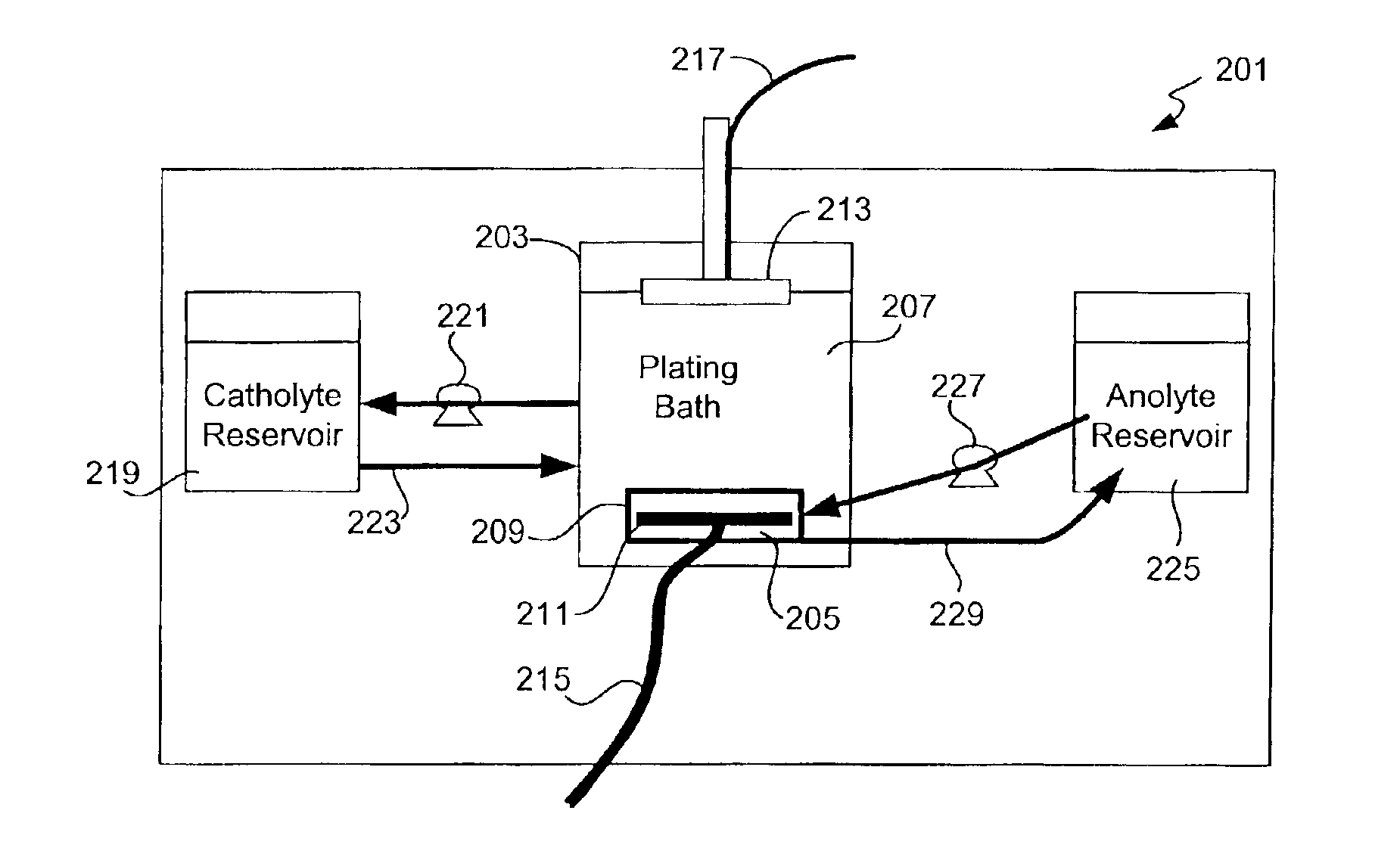
[0013]The present invention overcomes the above difficulties caused by anode mediated degradation of electrolyte additives by separating the electrolyte into a portion associated with the anode and a portion associated with the cathode (anolyte and catholyte, respectively). The separation is preferably accomplished by interposing a microporous chemical transport barrier (sometimes referred to as a diffusion barrier) between the anode and cathode. The transport barrier should limit the chemical transport (via diffusion and / or convection) of most species but allow migration of anion and cation species (and hence passage of current) during application of electric fields associated with electroplating. In other words, the transport barrier should limit the free cross-mixing of anolyte and catholyte.

Problems solved by technology

Particles that are often generated at the copper anode are prevented from passing into the cathode (wafer) chamber area and thereby causing a defect in the part.
Initially the anode contains no protective film and therefore the rate of additive consumption is high.
Furthermore, in most conventional designs, when plating is not performed in a cell, the anode is still immersed in the bath electrolyte.
Under these conditions, the anode protective film slowly degrades.

Method used


Image

  • Copper electroplating method and apparatus
  • Copper electroplating method and apparatus
  • Copper electroplating method and apparatus

Examples


example

[0115

[0116]FIG. 6 shows the comparative rate of additive concentration under similar bath conditions and currents for a Sabre™ tool (electroplating system available from Novellus Corporation of San Jose, Calif.). The lower line presents data obtained from a single bath reservoir for the anode and cathode electrolytes. The upper line presents data obtained from a small test cell (scaled version of the Sabre tool) with a ceramic separator placed between an anode chamber containing plating bath without organic additives and a plating chamber containing additive. Shipley Ultrafill™ was the bath chemistry used in both cases. At the beginning of the process, the concentration of acid and copper were the same in both the anolyte and catholyte chambers. The copper ion concentration was 18 g / l and the concentration of sulfuric acid was 180 g / l. The results show a 2 to 3 fold reduction in the rate of breakdown of accelerator material.

[0117]Other Embodiments

[0118]While this invention has been ...


PUM

PropertyMeasurementUnit
Compositionaaaaaaaaaa
Flow rateaaaaaaaaaa
Concentrationaaaaaaaaaa

Abstract

An electroplating apparatus prevents anode-mediated degradation of electrolyte additives by creating a mechanism for maintaining separate anolyte and catholyte and preventing mixing thereof within a plating chamber. The separation is accomplished by interposing a porous chemical transport barrier between the anode and cathode. The transport barrier limits the chemical transport (via diffusion and / or convection) of all species but allows migration of ionic species (and hence passage of current) during application of sufficiently large electric fields within electrolyte.

Description

CROSS-REFERENCE TO RELATED APPLICATION[0001]This is a divisional application Ser. No. 09 / 706,272 filed Nov. 03, 2000 now U.S. Pat. No. 6,527,920, claims priority under 35 USC 119(e) from U.S. Provisional Application No. 60 / 203,432, having Steven T. Mayer et al. as inventors, filed May 10, 2000, and titled “METHODS, MATERIALS, AND APPARATUS FOR IMPROVED COPPER ELECTROPLATING. Provisional Application No. 60 / 203,432 is incorporated herein by reference for all purposes.BACKGROUND OF THE INVENTION[0002]This invention relates to electroplating metal layers onto substrates and electropolishing metal layers on substrates. More specifically, it relates to apparatus for controlling the composition, flow, and potential distribution of electrolyte while electroplating or electropolishing a silicon wafer.[0003]Damascene processing is a method for forming metal lines on integrated circuits. It is a significant departure from traditional methods that require blanket deposition and subsequent patte...

Claims


Application Information

Patent Timeline
IPC IPC(8): C25D21/12C25F7/00H05K3/24
CPCC25D21/12C25F7/00H05K3/241
Inventor MAYER, STEVEN T.PATTON, EVAN E.JACKSON, ROBERT L.REID, JONATHAN D.
Owner NOVELLUS SYSTEMS
Learn More