
Radiation image sensor and scintillator panel

a technology of radiation image sensor and scintillator panel, which is applied in the field of image sensors, can solve the problems of insufficient strength and difficulty in forming the anti-moisture construction disclosed

Inactive Publication Date: 2005-05-10
HAMAMATSU PHOTONICS KK
View PDF23 Cites 19 Cited by
  • Summary
  • Abstract
  • Description
  • Claims
  • Application Information

AI Technical Summary

Benefits of technology

[0005]Accordingly, an object of the present invention is to provide a radiation image sensor and a scintillator panel that have protective means that offer durability and strength.
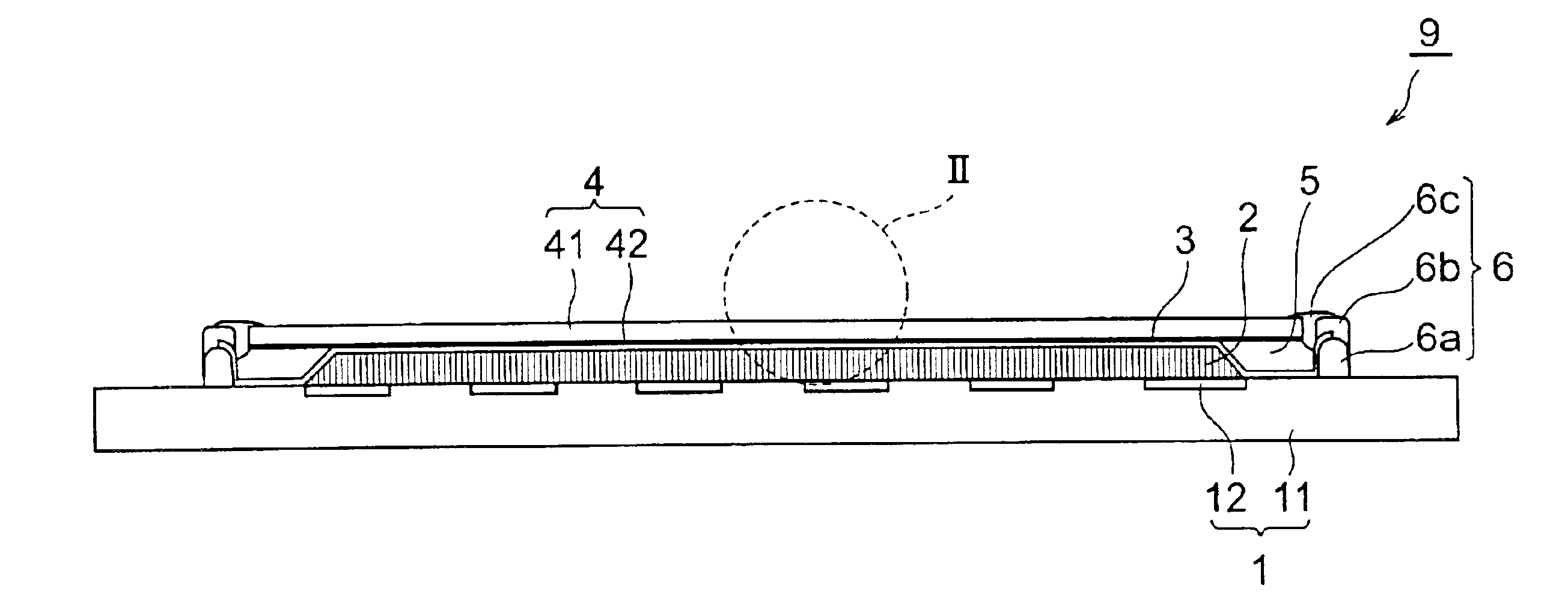
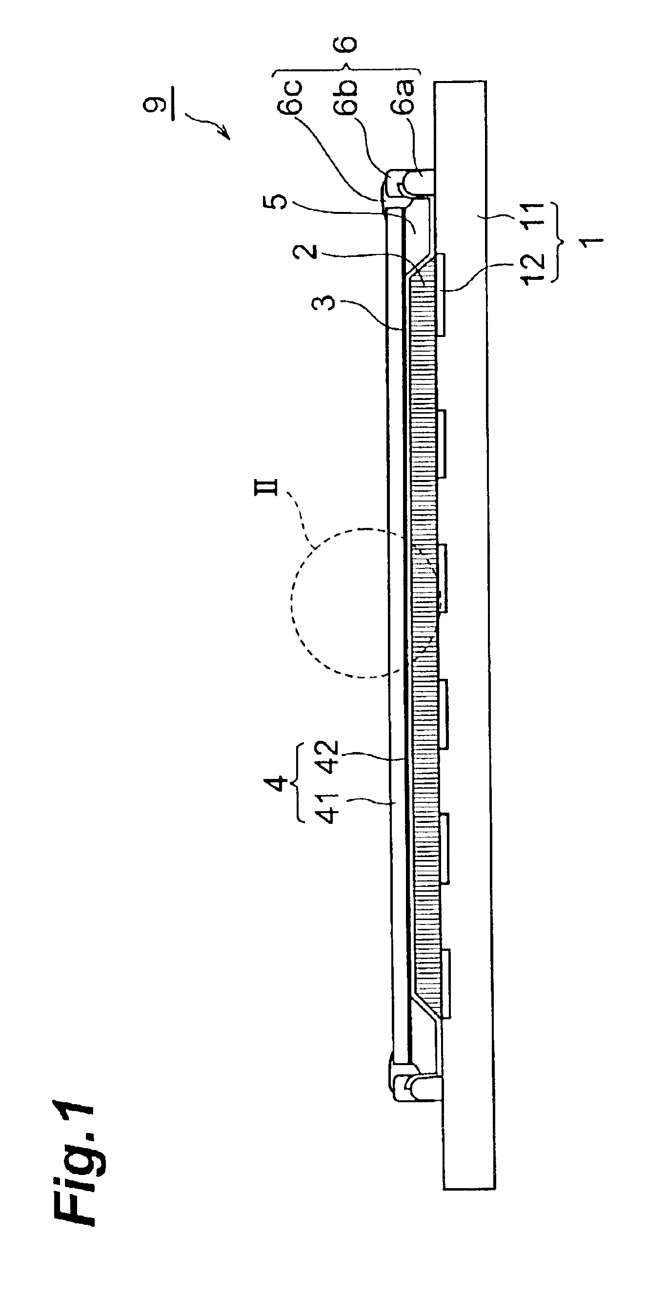
[0009]In the scintillator panel and radiation image sensor according to the present invention, because a protective film is formed so as to cover the scintillator and adhere thereto, the scintillator is well protected from atmospheric moisture. Moreover, because the protective film is covered by the radiation-transmittable plate fixed above the protective film, strength is ensured. Furthermore, because the protective film and the radiation-transmittable plate are fixed by the frame, manufacturing is made easy and the overall strength is increased.
[0010]It is preferred that openings be formed in part of the area between the frame and the radiation-transmittable plate. By forming such openings, because the space between the radiation-transmittable plate and the edges of the scintillators is not closed, when thermal processing or the like is carried out during manufacturing, deformation of or damage to the radiation-transmittable plate, the substrate or the image sensor is prevented.
[0012]When the radiation-transmittable plate is made a light-reflecting plate, because the light emitted by the scintillator and redirected toward the radiation incident surface is returned toward the scintillator, the output light intensity of the visible image output by the scintillator is improved.

Problems solved by technology

However, in the technologies disclosed in JP 05-196742A and in JP 05-242841A, it is not easy to form the anti-moisture construction disclosed therein.
WO-98 / 36290 and WO-98 / 36291, on the other hand, solve these problems, but offer insufficient strength.

Method used


Image

  • Radiation image sensor and scintillator panel
  • Radiation image sensor and scintillator panel
  • Radiation image sensor and scintillator panel

Examples


Embodiment Construction

[0024]The best mode for carrying out the present invention will be explained in detail below with reference to the drawings. To facilitate the comprehension of the explanation, the same reference numerals denote the same parts, where possible, throughout the drawings, and a repeated explanation will be omitted. Furthermore, the dimensions and configurations shown in the drawings are not necessarily accurate or true to scale, and some parts may be enlarged in order to facilitate understanding.

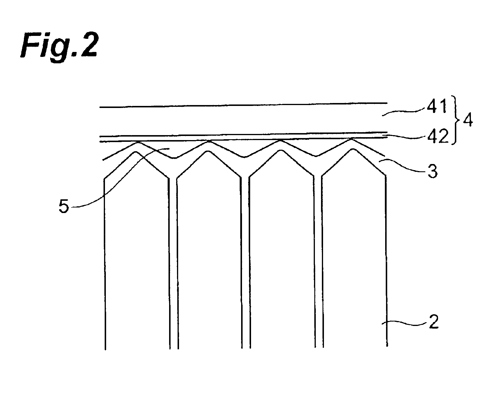
[0025]FIG. 1 is a cross-sectional view of a first embodiment of the radiation image sensor according to the present invention, FIG. 2 is an expanded view of a part thereof, and FIG. 3 is a top view thereof.

[0026]The solid imaging element 1 of this radiation image sensor 9 comprises a substrate 11 formed from an insulating material such as glass and a light receiving unit wherein light receiving elements 12 that carry out photoelectric conversion are arranged two-dimensionally on the substrate. T...


PUM


Abstract

A radiation image sensor comprises (1) an image sensor 1 having a plurality of light receiving elements arranged in one or two dimensionally, (2) scintillator 2 having columnar structure formed on the light-receiving surface of this image sensor 1 to convert radiation into light that can be detected by the image sensor 1, (3) a protective film 3 formed so as to cover and adhere to columnar structure of scintillator 2, (4) a frame 6 disposed around the scintillator to set separation distance from the scintillator and fix the protective film onto the image sensor, and (5) a radiation-transmittable plate 4 fixed opposite to the image sensor 1 by the frame 6 to sandwich the protective film 3 therebetween.

Description

TECHNICAL FIELD[0001]The present invention relates to an image sensor that detects radiation images used in medical and other fields, as well as to a scintillator panel that converts radiation images into visible light images that can be detected by an image sensor.BACKGROUND ART[0002]X-ray sensitive film has been used in X-ray imaging conventionally employed for medical and industrial purposes, but radiation imaging systems that use a radiation detecting element have become increasingly popular from the standpoint of convenience and durability of the imaging result. In this type of radiation imaging system, two-dimensional image data derived from radiation is obtained as electrical signals using a radiation detecting element having a plurality of pixels, these signals are processed by a processing apparatus and displayed on a monitor. A representative radiation detecting element has a construction in which scintillator is incorporated in light detectors arranged in a one-dimensiona...

Claims


Application Information

Patent Timeline
Patent Type & Authority Patents(United States)
IPC IPC(8): G01T1/20G01T1/24G01T1/00H05G1/64H05G1/00
CPCG01T1/2018G01T1/20189G01T1/20
Inventor SUZUKI, TAKAHARU
Owner HAMAMATSU PHOTONICS KK
Learn More