Pilot signals for synchronization and/or channel estimation
a pilot signal and channel estimation technology, applied in the field of communication systems, can solve the problems of difficult to achieve channel estimation for coherent detection, received signal suffers from frequency selective multipath fading, and is difficult to predict its behavior, so as to eliminate or prevent sidelobes, the effect of optimal autocorrelation results
- Summary
- Abstract
- Description
- Claims
- Application Information
AI Technical Summary
Benefits of technology
Problems solved by technology
Method used
Image
Examples
first embodiment
for Odd Numbered Slots
[0280]The present invention results in 15 slot-length pilot pattern having a minimum side lobe coefficient, and is optimal to frame synchronization for physical channel of up-link or down-link when the chip rate is 3.84 Mcps instead of 4.09 Mcps (16 slot-length). Such correlation characteristic of the pilot pattern can be alternatively explained based on the following for a slot length of 2l+1 (l=1,2,3,4, . . . ) including L=15 when l=7.
[0281]First, when a length of a sequence having a minimum side lobe value is defined as 2l+1 and the sequence with the length of 2l+1 be C1, the auto correlation value of C1 is expressed by the following:
RC1(j)=(2l+1)−4z(4z=0,4,8,16, . . . ) (20)
where the maximum auto correlation value of sequence C1 is 2l+1, and the auto correlation value corresponds to a value obtained by reducing a multiple of 4 from the maximum correlation value. Here, if l is an odd number, e.g., l=7, l may be expressed as l=2i+1 (i=0,1,2,3, . . . ). Acco...
second embodiments
1. Second Embodiments for Odd Numbered Slots
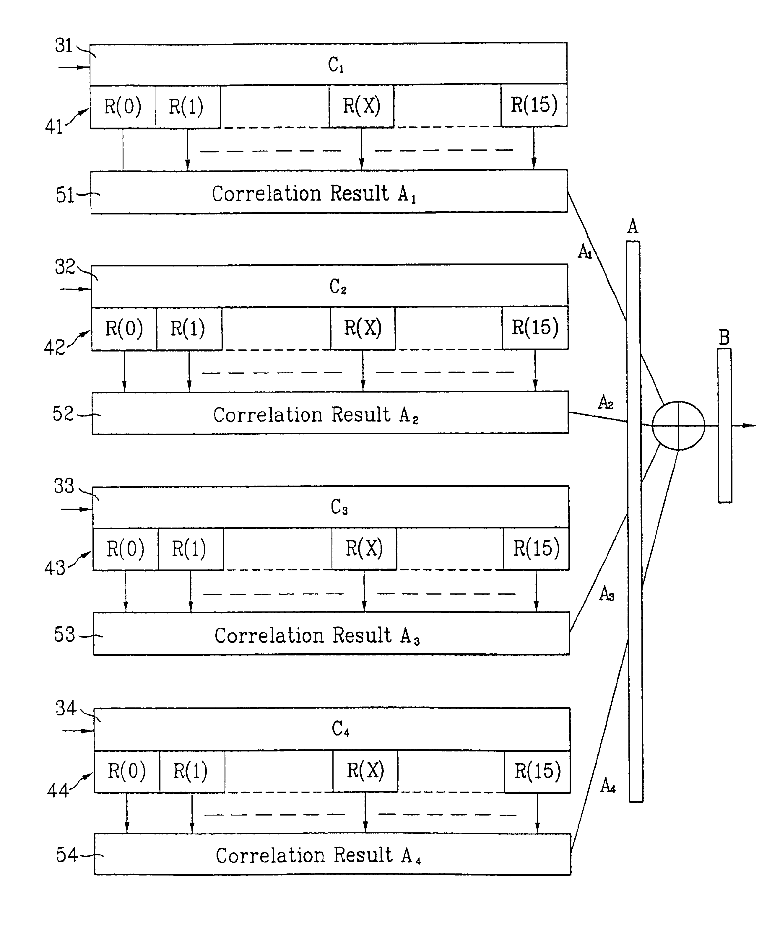
[0312]A method of confirming a frame synchronization through a use of correlation results based on respective slots is described in the following preferred embodiments. An optimum pilot pattern is used to confirm a frame synchronization, in using a chip ratio of 3.84 Mcps instead of a chip ratio of 4.096 Mcps as a length of 16 slots, in the physical channel of an up-link or down-link.
[0313]The pilot pattern of the 15-slot length shown in FIG. 21 can be expressed based on a correlation process as shown below in Table 10.
[0314]
TABLE 10column sequence (15-slots length)C1 = (a1, a3, a5, . . . , a29) = (100011110101100)C2 = (a2, a4, a6, . . . , a30) = (101001101110000)C3 = (b1, b3, b5, . . . , b29) = (110001001101011)C4 = (b2, b4, b6, . . . , b30) = (001010000111011)C5 = (c1, c3, c5, . . . , c29) = (111010110010001)C6 = (c2, c4, c6, . . . , c30) = (110111000010100)C7 = (d1, d3, d5, . . . , d29) = (100110101111000)C8 = (d2, d4, d6, . . . , d30) ...
PUM
 Abstract
Description
Claims
Application Information
 - R&D
- Intellectual Property
- Life Sciences
- Materials
- Tech Scout
- Unparalleled Data Quality
- Higher Quality Content
- 60% Fewer Hallucinations
Browse by: Latest US Patents, China's latest patents, Technical Efficacy Thesaurus, Application Domain, Technology Topic, Popular Technical Reports.
© 2025 PatSnap. All rights reserved.Legal|Privacy policy|Modern Slavery Act Transparency Statement|Sitemap|About US| Contact US: help@patsnap.com


