Lamp monitoring and control system and method

a technology for monitoring and controlling systems and street lamps, applied in the direction of electric testing/monitoring, digital computer details, instruments, etc., can solve the problems of no centralized monitor and control mechanism, no standard starting circuit for mercury-vapor lamps, and labor-intensive monitoring and control functions of early street lamps, so as to reduce the probability of collisions, improve the probability of packet reception, and provide centralized monitoring and/or control

Inactive Publication Date: 2005-05-10
A L AIR DATA
View PDF58 Cites 64 Cited by
  • Summary
  • Abstract
  • Description
  • Claims
  • Application Information

AI Technical Summary

Benefits of technology

[0042]An advantage of the present invention is that it solves the problem of efficiently providing centralized monitoring and / or control of the street lamps in a geographical area.
[0043]Another advantage of the present invention is that by randomizing the frequency and timing of redundant transmissions, it reduces the probability of collisions while increasing the probability of a successful packet reception.
[0044]An additional advantage of the present invention is that it provides for a new type of monitoring and control unit which allows centralized monitoring and / or control of units distributed over a large geographical area.
[0045]Another advantage of the present invention is that it allows bases stations to be connected to other base stations or to a main station in a network topology to increase the amount of monitoring data in the overall system.
[0046]A feature of the present invention, in accordance with one embodiment, is that it includes the base station with an ID and status processing unit for processing the ID field of the monitoring data.
[0047]Another feature of the present invention is that in accordance with an embodiment, the monitoring data further includes a data field which can store current or voltage data in a lamp monitoring and control system.

Problems solved by technology

This monitor and control function of the early street lamps was very labor intensive since each street lamp had to be individually lit (controlled) and watched for any problems (monitored).
Unfortunately, these street lamps still had the same problem as the original lanterns in that there was no centralized monitor and control mechanism to light the street lamps at night and watch for problems.
Unfortunately, there is no standard starting circuit for mercury-vapor lamps.
Typically, the lamp current is limited by a resistor, which severely reduces the efficiency of the circuit, or by a magnetic device, such as a choke or a transformer, called a ballast.
Because of the variety of different types of starter circuits, it is virtually impossible to characterize the current and voltage characteristics of the mercury-vapor lamp.
In fact, the mercury-vapor lamp may require minutes of warm-up before light is emitted.
Additionally, if power is lost, the lamp must cool and the mercury pressure must decrease before the starting arc can start again.
All of these types of lamps require a starting circuit which makes it virtually impossible to characterize the current and voltage characteristics of the lamp.
Lamp sensor unit 210 provides an automated, distributed control mechanism to turn lamp assembly 230 on and off Unfortunately, it provides no mechanism for centralized monitoring of the street lamp to determine if the lamp is functioning properly.
When a street lamp burns out over a highway, it is often not replaced for a long period of time because the maintenance crew will only schedule a replacement lamp when someone calls the city maintenance department and identifies the exact pole location of the bad lamp.
Since most automobile drivers will not stop on the highway just to report a bad street lamp, a bad lamp may go unreported indefinitely.
Additionally, if a lamp is producing light but has a hidden problem, visual monitoring of the lamp will never be able to detect the problem.
Some examples of hidden problems relate to current, when the lamp is drawing significantly more current than is normal, or voltage, when the power supply is not supplying the appropriate voltage level to the street lamp.
Furthermore, the present system of lamp control in which an individual light sensor is located at each street lamp, is a distributed control system which does not allow for centralized control.
For example, if the city wanted to turn on all of the street lamps in a certain area at a certain time, this could not be done because of the distributed nature of the present lamp control circuits.
Unfortunately, the RadioSwitch is unable to address most of the problems listed above.
Furthermore, since the communication link for the RadioSwitch is via paging networks, it is unable to operate in areas in which paging does not exist (for example, large rural areas in the United States).
Accordingly, installation is difficult because it cannot be used as a plug-in replacement for the current lamp control units.

Method used


Image

  • Lamp monitoring and control system and method
  • Lamp monitoring and control system and method
  • Lamp monitoring and control system and method

Examples


Embodiment Construction

[0068]The preferred embodiments of a lamp monitoring and control system (LMCS) and method, which allows centralized monitoring and / or control of street lamps, will now be described with reference to the accompanying figures. While the invention is described with reference to an LMCS, the invention is not limited to this application and can be used in any application which requires a monitoring and control system for centralized monitoring and / or control of devices distributed over a large geographical area. Additionally, the term street lamp in this disclosure is used in a general sense to describe any type of street lamp, area lamp, or outdoor lamp.

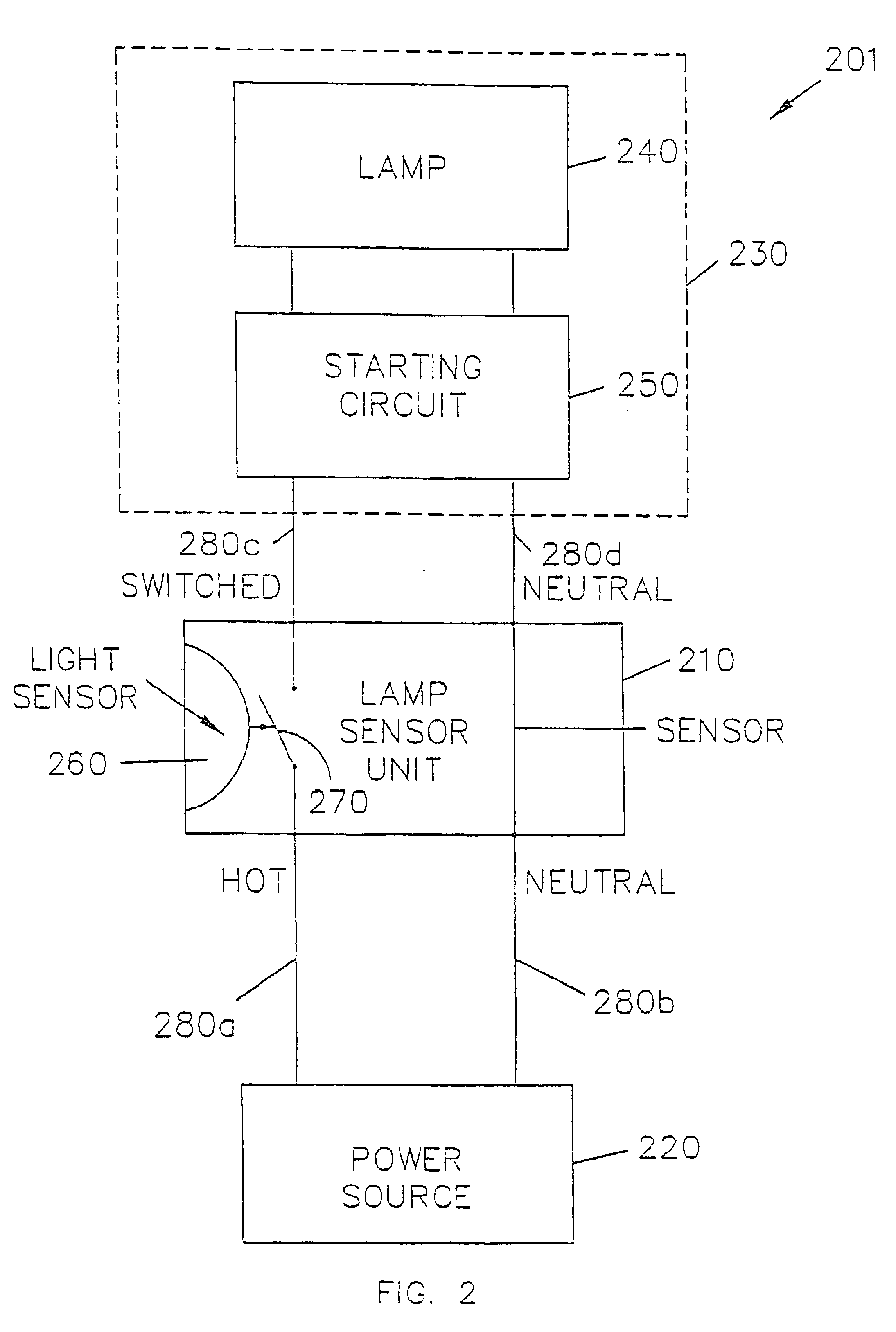
[0069]FIG. 3 shows a lamp arrangement 301 which includes lamp monitoring and control unit 310, according to one embodiment of the invention. Lamp monitoring and control unit 310 is situated between a power source 220 and a lamp assembly 230. Lamp assembly 230 includes a lamp 240 and a starting circuit 250.

[0070]Power source 220 may be a ...


PUM


Abstract

A system and method for remotely monitoring and / or controlling an apparatus and specifically for remotely monitoring and / or controlling street lamps. The lamp monitoring and control system comprises lamp monitoring and control units, each coupled to a respective lamp to monitor and control, and each transmitting monitoring data having at least an ID field and a status field; and at least one base station, coupled to a group of the lamp monitoring and control units, for receiving the monitoring data, wherein each of the base stations includes an ID and status processing unit for processing the ID field of the monitoring data.

Description

CROSS-REFERENCE TO RELATED APPLICATIONS[0001]The present application is a continuation of application Ser. No. 10 / 628,353 filed Jul. 29, 2003, now U.S. Pat. No. 6,807,516 publication No. US 2004 / 0073406A1; which is a continuation of application Ser. No. 10 / 118,324 filed Apr. 9, 2002, now U.S. Pat. No. 6,604,062; which is a continuation of application Ser. No. 09 / 576,545 filed May 22, 2000, now U.S. Pat. No. 6,370,489; which is a division of application Ser. No. 09 / 465,795 filed Dec. 17, 1999, now U.S. Pat. No. 6,415,245; which is a division of application Ser. No. 08 / 838,303 filed Apr. 16, 1997, now U.S. Pat. No. 6,035,266. The present application is related to application Ser. No. 10 / 811,855 filed Mar. 30, 2004, entitled “Remotely Controllable Distributed Device Monitoring Unit and System,” currently pending; which is a continuation of application Ser. No. 10 / 251,756 filed Sep. 23, 2002, now U.S. Pat. No. 6,714,895; which is a continuation of application Ser. No. 09 / 605,027 filed J...

Claims


Application Information

Patent Timeline
Patent Type & Authority Patents(United States)
IPC IPC(8): G05B23/02H05B37/02H05B37/00H05B37/03
CPCH05B37/0245H05B37/034H05B37/0272Y02B20/72H05B47/175H05B47/19H05B47/22
Inventor WILLIAMS, LARRYYOUNG, MICHAEL F.
Owner A L AIR DATA
Why Eureka
Try Eureka