
Piloted drill barrel and method of using same

Inactive Publication Date: 2005-05-17
BECK III AUGUST H
View PDF26 Cites 15 Cited by
  • Summary
  • Abstract
  • Description
  • Claims
  • Application Information

AI Technical Summary

Benefits of technology

[0009]Accordingly, an object of the present invention is to provide an improved large diameter hard rock drill barrel suitable for large diameter applications having lower air and fuel consumption than conventional large diameter gang drills.
[0023]One side of the pilot may be provided with a shim which is placed on the side of the pilot opposite the downhole hammer to bias the hammer away from the longitudinal axis of the pilot shaft, thereby excavating a slightly larger diameter shaft to accommodate casing placed in the shaft. Such casing may be desirable when drilling through soft overburden to keep water and earthen slough from intruding into the shaft. After the placement of the casing, the shim is placed on the side of the pilot nearest the hammer, forcing the hammer closer to the axis of the pilot shaft to drill a slightly smaller diameter. In the latter configuration, the barrel may be placed inside the casing and advanced therethrough to drill beyond the casing, while the casing protects against encroachment of the overburden into the shaft.

Problems solved by technology

The foregoing cutting techniques generally require extreme pressure exerted against the core barrel by the drive mechanism, and removal of the core can be very difficult.
Greater diameters are impractical due to the excessive cost of larger-diameter drill bits, expensive large downhole hammers and increased compressed air requirements.
For relatively large diameter shafts, e.g., 36 inches and greater, the number and size of hammer drills required make their use impractical because air and fuel consumption tends to be quite high.
In addition, gang drills suffer from disadvantages such as high cost and high maintenance, with attendant high out-of-service times. Also, gang drills lose efficiency when excavating on sloped or uneven ground.
All the hammer bits that are not in contact with the ground at a given time will blow off air and severely impair the hammering ability of the hammer bits that are in contact with the rock.
Also, the smaller diameter shanks tend to break off when subjected to side loads during rotation of the barrel, resulting in bit replacement and possible expensive retrieval operations.
Moreover, none of the foregoing prior art tools can drill shafts of different diameters, and thus they are unsuited to drilling shaft portions into which casing is to be placed before further drilling takes place.
Also, in a vertical or near-vertical shaft, the foregoing drills can not carry cuttings to the surface without adding a calix basket or other catchment to the top of the tool for carrying out cuttings that are not blown out of the shaft.
This makes the overall height of the tool so tall as to interfere with the underside of the rotary table on conventional foundation drill machines, making it difficult to clear the tool from the excavation to dump the cuttings, remove the tool, or inspect the tool.

Method used


Image

  • Piloted drill barrel and method of using same
  • Piloted drill barrel and method of using same
  • Piloted drill barrel and method of using same

Examples


Embodiment Construction

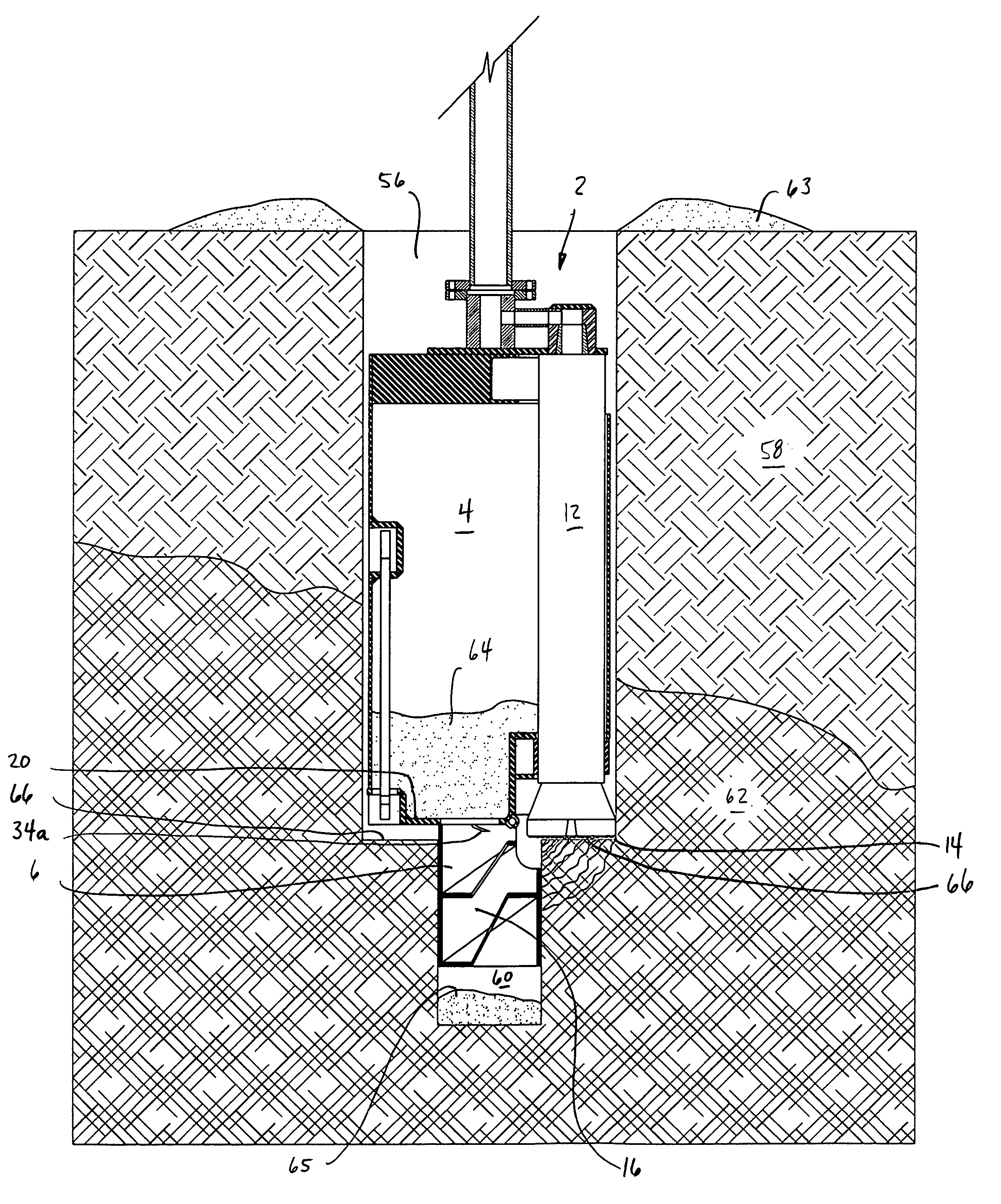
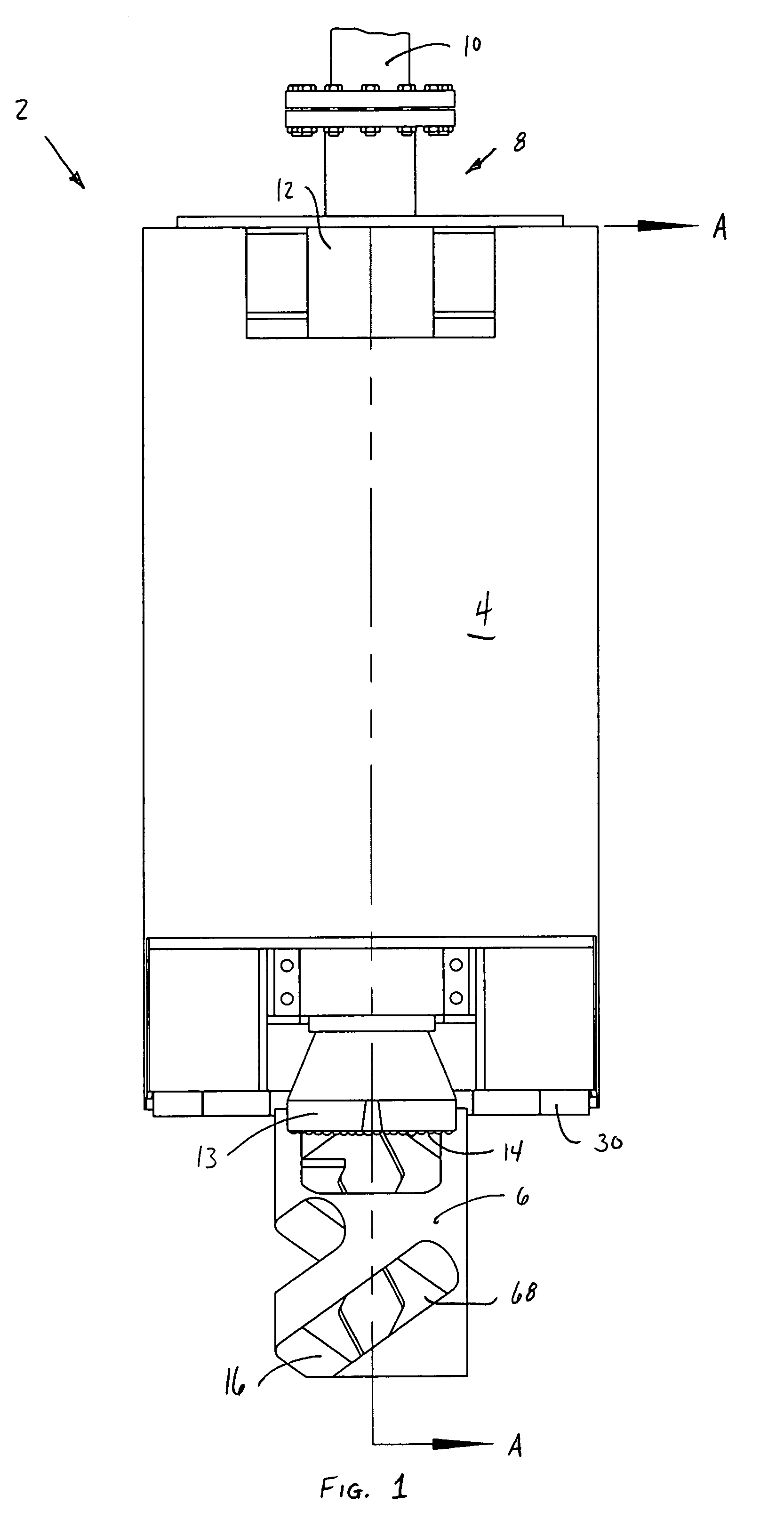
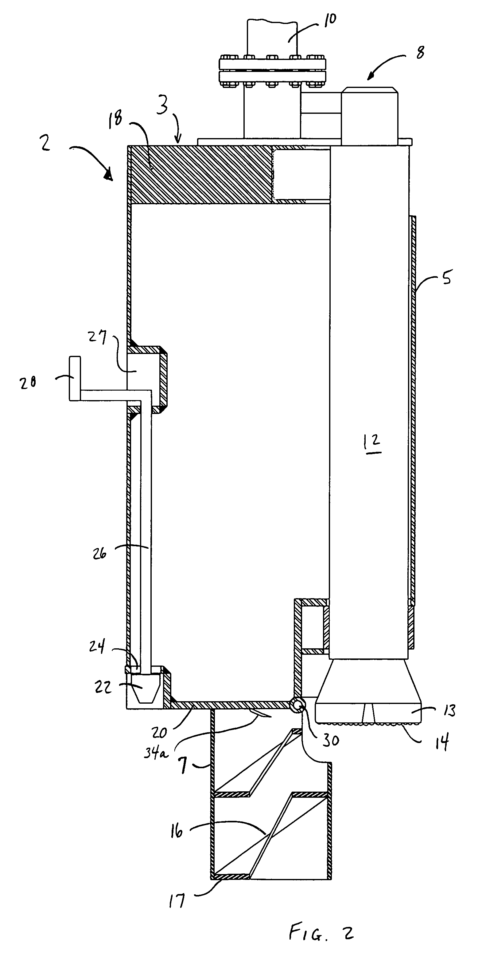
[0042]Referring in more detail to the drawings, there is shown in FIGS. 1 and 2 a piloted drill barrel 2 having a barrel portion 4 and a pilot portion 6. The barrel portion 4 will have an outer diameter slightly less than the diameter of the shaft to be drilled, and about 40.5 inches in the preferred embodiment. Barrel wall 5 will be of a suitable thickness in view of the particular requirements of the excavation, and is about one inch in the preferred embodiment. Downhole hammer drill 12 is suspended rigidly inside barrel portion 4 near its periphery. Hammer drill 12 may be any pressurized air drill suitable for drilling into hard rock. One such drill that has provided acceptable results is available from Ingersoll-Rand and designated model no. QL-120. An assortment of drill bits is available for such drills. A 15 inch-diameter QL-120 drill bit with tungsten carbide buttons at cutting face 14 has proved satisfactory, although the bit selected will depend on several factors, includi...


PUM


Abstract

A hard rock drill barrel has a barrel portion with a downhole hammer drill disposed therein at the barrel's periphery. A pilot portion, in substantial axial alignment with the barrel but having a smaller diameter, extends distally from the barrel for inserting into a pilot shaft of slightly larger diameter than the pilot portion. In operation, the hammer drill excavates a collar around the pilot shaft when the drill barrel is rotated and supplied with pressurized air, thereby excavating a relative large diameter shaft. The drill barrel is hollow and open at its proximal end to receive and collect cuttings flushed into the shaft above the drill barrel. The piloted drill barrel is adjustable to excavate variable diameter shaft portions, enabling the placement of casing within a larger diameter shaft portion. After adjustment of the drill barrel, smaller-diameter shaft excavation proceeds beyond the casing.

Description

FIELD OF THE INVENTION[0001]The invention relates generally to drilling apparatus for excavating relatively large diameter shafts into hard rock, and more particularly to drilling barrels equipped with a downhole hammer.BACKGROUND OF THE INVENTION[0002]In the foundation drilling industry and in the boring and tunneling industry, it is desired to excavate large diameter shafts (on the order of 36 inches to 84 inches diameter and up) penetrating into very hard rock. In the foundation drilling industry, these shafts are typically filled with reinforced concrete to form foundation piles for buildings, bridges, etc, while in the boring and tunneling industry, these shafts are typically used as access shafts, utility shafts, ventilation shafts, personnel entry shafts or elevator shafts. Often rock augers are used, equipped with tungsten carbide cutting edges. When the rock becomes very hard, the progress of the excavation will virtually stop or reach excavating rates less than 2″ per five...

Claims


Application Information

Patent Timeline
IPC IPC(8): E21B7/00E21B17/00E21B17/10E21B27/00E21B4/20E21B4/00E21B27/04
CPCE21B4/20E21B7/00E21B7/003E21B27/04E21B17/10E21B27/00E21B7/006
Inventor BECK, III, AUGUST H.
Owner BECK III AUGUST H
Learn More