[0021]In one aspect, the present invention is a structural characteristic of a fuel-
cell flowfield that provides an automatic self-correcting clog-removal mechanism that facilitates the removal of
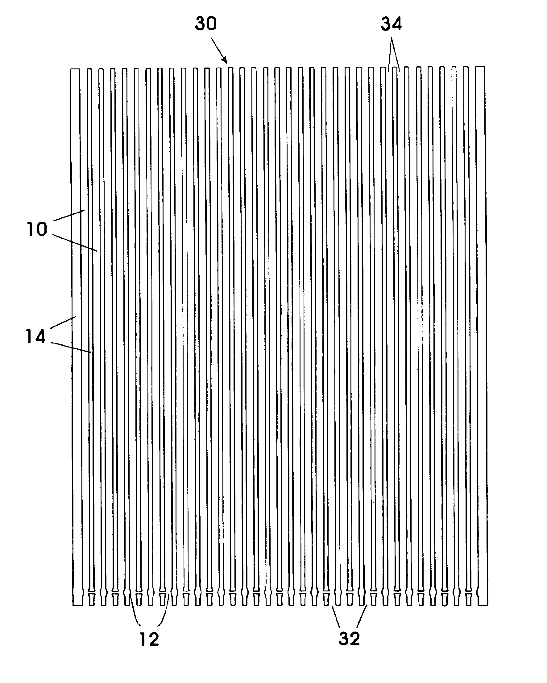
excess water from the flowfield channels. The novel structure is a duct connecting two channel regions (typically, a leg in each of two neighboring channels) for transferring water between the two channel regions and for slowing the formation of water clogs in the channels.
[0024]A duct or ducts connecting channel regions may effectively reduce local flooding and enhance fuel cell performance. Typically, with multiple channel flowfields, when blockage in one channel inhibits reactant gas flow in that channel, reactant gas tends to be diverted to one or more unblocked channels with a resulting increased flow velocity in the unblocked channel or channels. The increased flow velocity in the other unblocked channels increases the flow-velocity-induced pressure differential as between the vicinity of the duct end opening in the blocked channel and the vicinity of the duct end opening in the unblocked channel, dynamically enhancing the water drawing effect of a duct connecting the two channels responsive to the extent to which flow in the blocked channel is inhibited. In this way, a duct connecting two channel regions in a flowfield may automatically remove accumulated water so as to reduce localized flooding.
[0025]Ducts connecting channels in a flowfield may also slow the formation of water clogs in the channels, in that when the flow velocities in duct-connected channel regions are roughly similar, the ducts operate to equalize the reactant
gas pressure in the connected channel regions. Depending on the number of ducts and the location of the end openings of the ducts, this pressure
equalization may operate to ensure that the channels in a flowfield have adequate pressure at key locations of the flowfield and adequate pressure drop throughout the length of the channels. The duct-produced pressure
equalization thereby helps to maintain a desired flow of reactant gas along each channel, which helps propel
excess water along the channels, and, when the oxidant is
oxygen in air, helps prevent localized oxygen depletion.
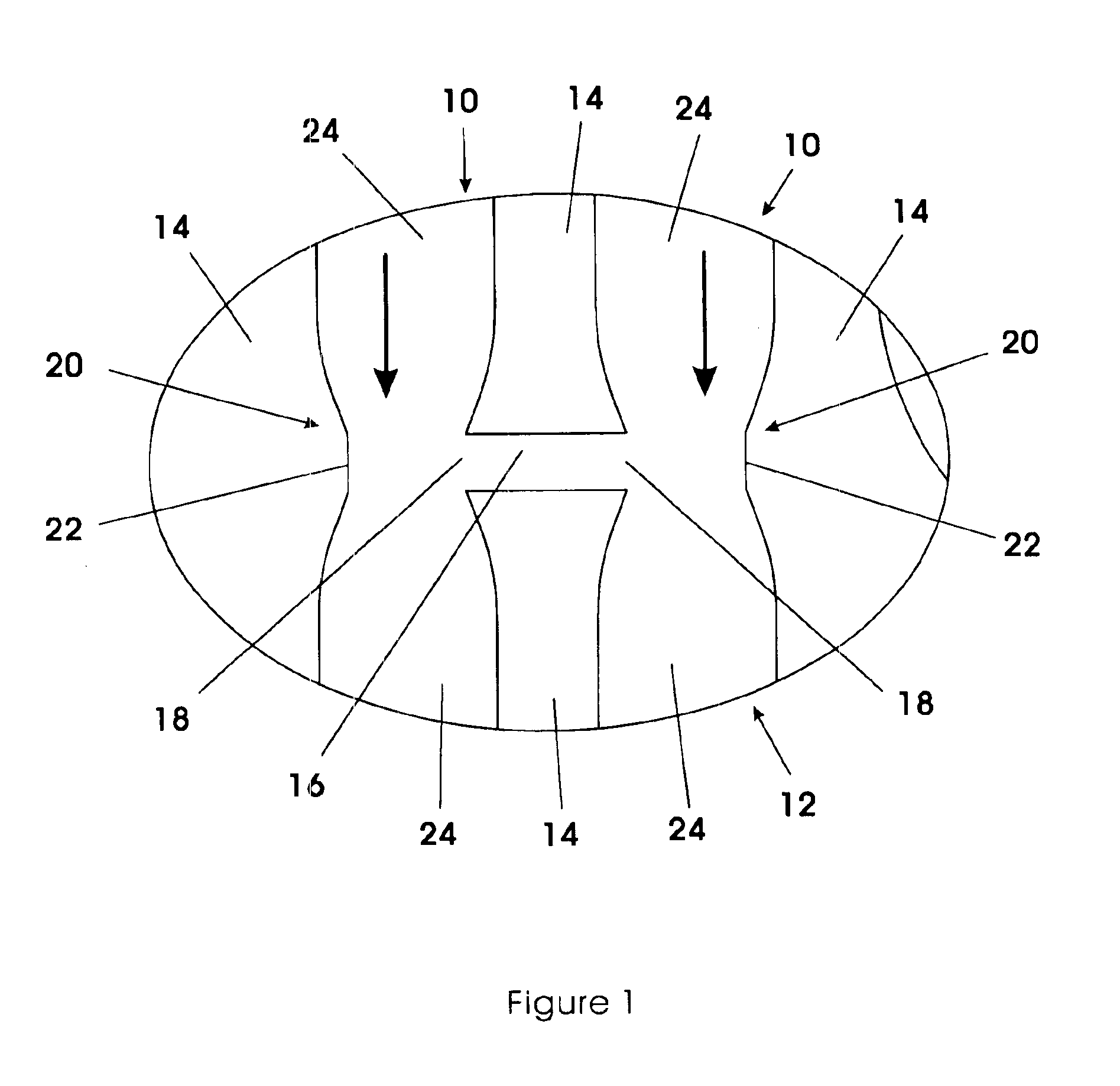
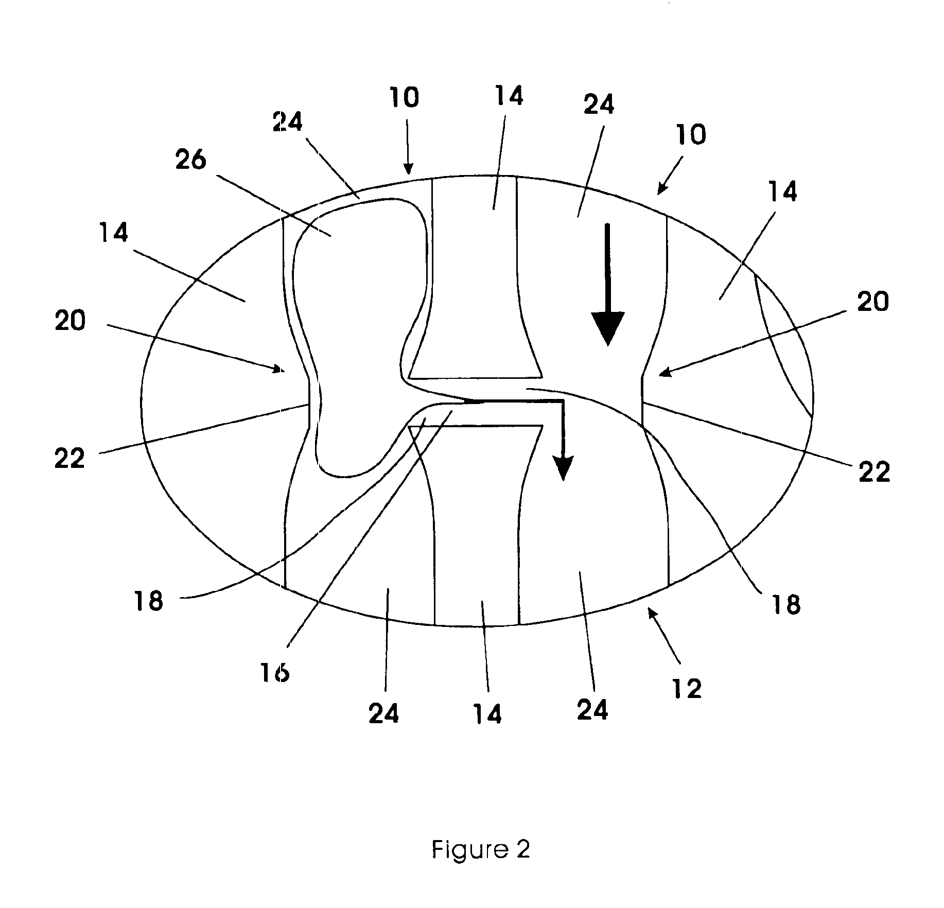
[0028]Each duct end opening may be associated with a means for increasing the flow velocity (and thus reducing the pressure) of the reactant gas in the associated channels in the vicinity of the duct end opening. Preferably, each such flow-velocity increasing means is a venturi or tapered narrowing of the channel, with each duct end opening located at or near the narrowest portion or
throat of the associated venturi. When the flow velocity in each of two duct-connected channel regions is roughly the same, the venturis at the end openings of the duct increase the flow velocity within each venturi, and thereby reduce the pressure at each duct end opening, by a roughly equal amount, which does not induce any flow between the channel regions via the duct. When the flow velocity of one channel region is reduced by a water blockage in that channel and is less than the other channel region, in the channel region with the higher flow velocity, the venturi-induced increase in flow velocity and resulting pressure drop enhance the drawing of water from the channel region with the lower flow velocity. The venturi-induced enhancement of
water transfer via a duct is most significant when the flow velocity approaches zero in the channel region with the lower flow velocity. However, the increase in flow velocity (and thus the decrease in pressure) induced by the venturi is proportional to the flow velocity immediately upstream of the venturi. Therefore, a venturi at each duct end opening tends to amplify the flow-velocity differential (and resulting pressure differential) between two duct-connected channels, and the duct / venturis combination is more sensitive to obstruction-induced flow-velocity decreases than a duct alone. The introduction of venturis into the channels in a flowfield may increase the manufacturing cost of the flowfield plate, and this possible added cost must be weighed against the enhancement in fuel cell performance obtained through the venturis, which will vary depending on the flowfield pattern etc.
[0029]The flow of fluid in and out of a duct; the interruption of a channel wall that is a duct end opening; and a venturi, may all act to improve the flow regime of a reactant gas, particularly oxidant air. These structural and operational characteristics all tend to disrupt the laminar flow of the air, and thus induce mixing of the oxidant air
stream, which helps prevent a depletion of oxygen at the air-to-MEA interface.
[0030]Comparative experiments conducted by the inventors have indicated that the introduction of a duct (or more typically, ducts) between channels in a flowfield improves fuel cell electrochemical reaction and power generation performance.

