Induction heating apparatus

a technology of heating apparatus and heating coil, which is applied in the direction of heating types, lighting and heating apparatus, and domestic stoves or ranges. it can solve the problems of affecting the normal operation of the heating coil, the inability to cook small amounts of food and the inability to carry out cooking using a non-magnetic pan. it can prevent the abnormal temperature rise

Inactive Publication Date: 2005-05-17
PANASONIC CORP
View PDF10 Cites 14 Cited by
  • Summary
  • Abstract
  • Description
  • Claims
  • Application Information

AI Technical Summary

Benefits of technology

[0018]An object of the present invention is to provide an induction heating cooking appliance having a temperature control function such that an abnormal temperature rise can be prevented in the case that a pan made of a non-magnetic material, e.g., aluminum, is used for cooking.

Problems solved by technology

Consequently, a repulsive force occurs between the pan and the heating coil due to magnetism.
In the induction heating cooking appliance of the above-mentioned first prior art, the high frequency current is cut when the weight of the pan including its contents is a predetermined value or less, and therefore, cooking using a non-magnetic pan cannot be carried out.
A non-magnetic pan, for example, cannot be used for cooking a small amount of food material for a family of a small number of people.
Therefore, the user cannot cook with a light pan for a small amount of food material.
It is not easy, however, to directly measure the temperature of the food material.
Then, the temperature sensor cannot correctly detect the temperature of the bottom of the pan.
Such being the case, correct temperature control is not carried out, and there is a risk wherein the temperature of the pan and the temperature of the object to be heated may rise in an abnormal level.
Therefore, temperature sensor 57 cannot precisely detect the temperature of object 51 to be heated, and temperature control suffers harmful influences.
This is a significant problem, wherein such a structure is disadvantageous in order to achieve successful cooking when using the induction heating cooking appliance.

Method used


Image

  • Induction heating apparatus
  • Induction heating apparatus
  • Induction heating apparatus

Examples


first embodiment

[First Embodiment]

[0066]An induction heating cooking appliance having a temperature control function according to the first embodiment of the present invention is described in reference to FIG. 1 to FIG. 4.

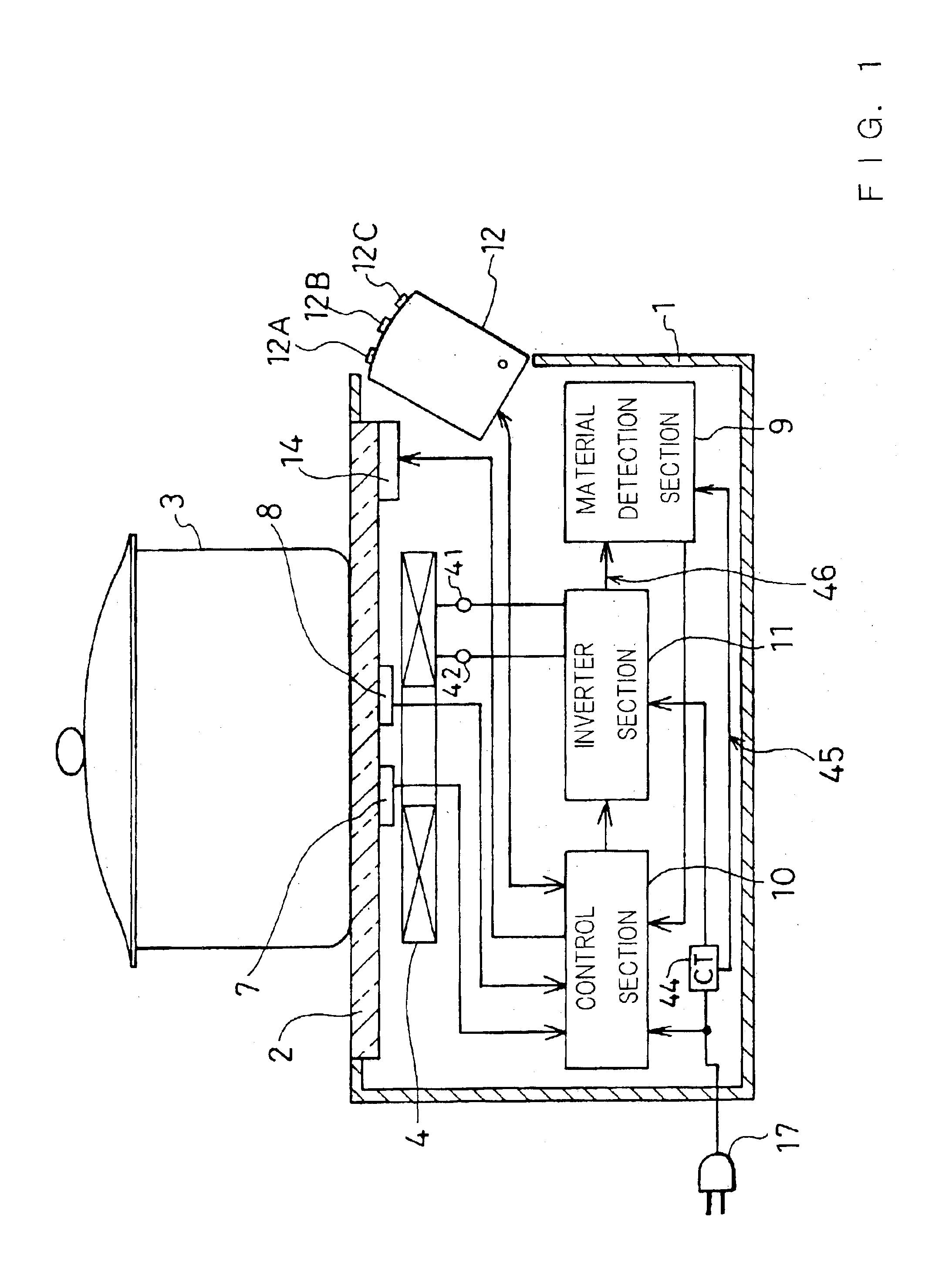
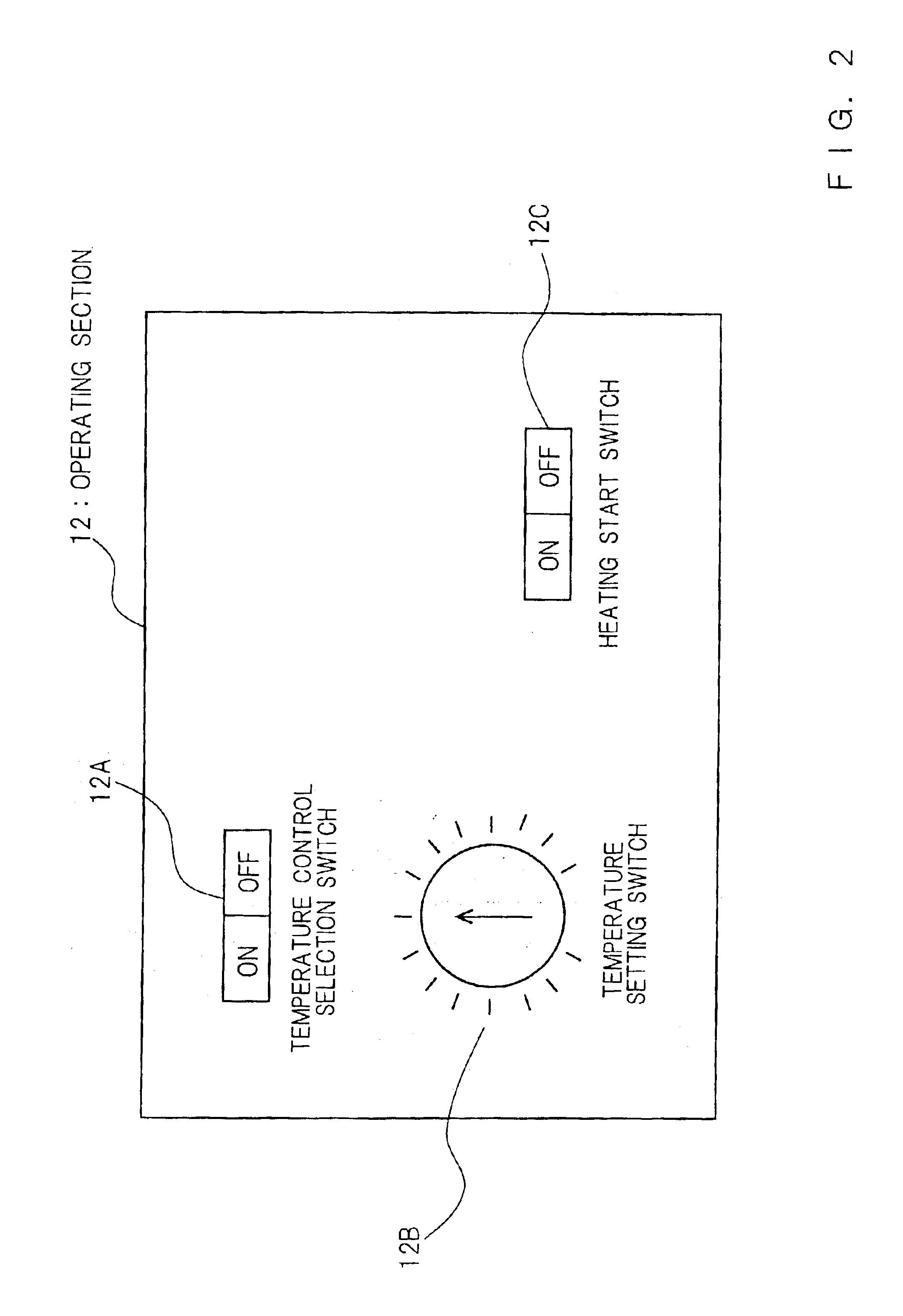
[0067]FIG. 1 is a cross sectional view of an induction heating cooking appliance of the present embodiment. In the figure, a top plate 2 made of heat-resistant glass or the like is attached to the top portion of a housing 1, and the user places a pan 3 or the like on top plate 2 to heat the pan for cooking. An induction heating coil 4 is disposed in a housing 1 beneath top plate 2 so as to keep a predetermined distance between induction heating coil 4 and pan 3. A predetermined position for placing pan 3 is indicated on the upper surface of top plate 2 with a pattern, such as a circle (not shown). A temperature sensor 7 and a pan floating detector 8 are disposed on the lower surface of top plate 2. Temperature sensor 7 detects the temperature of the bottom of pan 3 via top plate 2...

second embodiment

[Second Embodiment]

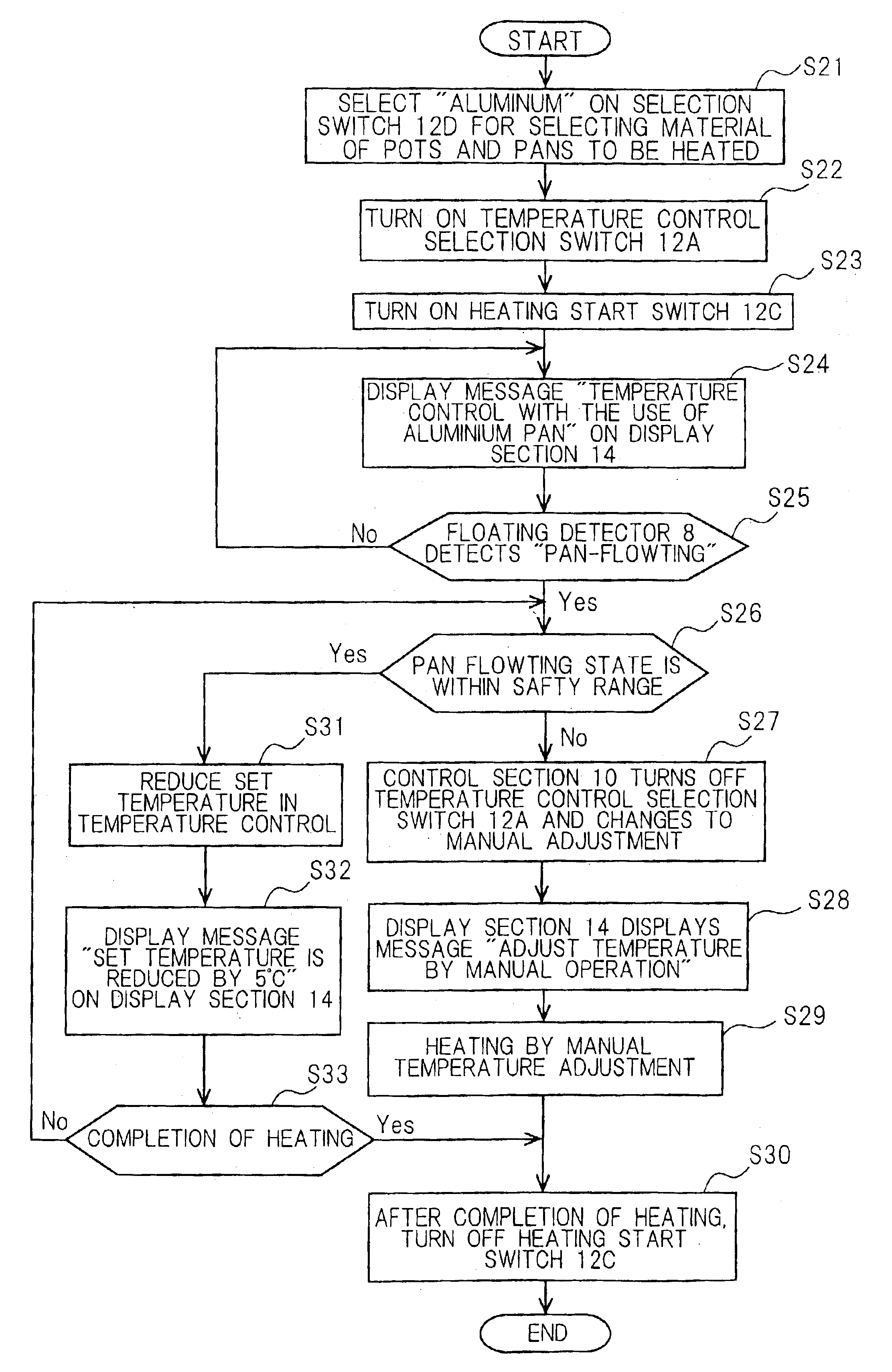
[0081]An induction heating cooking appliance having a temperature control function according to the second embodiment of the present invention is described in reference to FIG. 1, FIG. 5 and FIG. 6. The induction heating cooking appliance of the second embodiment is provided with an operation section 22 shown in FIG. 5 in place of operating section 12 in FIG. 1. Operating section 22 is provided with an object to be heated selection switch 12D. The other parts of the configuration are substantially the same as in the first embodiment shown in FIG. 1. Object to be heated selection switch 12D is connected to control section 10 shown in FIG. 1 and control section 10 has a control function for controlling inverter section 11, as described in detail in the following.

[0082]Object to be heated selection switch 12D is a switch operated by the user which uses an object to be heated, such as pan 3 made of a material having a conductivity approximately the same as, or greater...

third embodiment

[Third Embodiment]

[0089]FIG. 7 is a block diagram showing the configuration of an induction heating apparatus according to the third embodiment of the present invention.

[0090]In FIG. 7, the induction heating apparatus, such as an induction heating cooking appliance of the present embodiment, has a configuration of which first and second objects 30 and 31 to be heated of different types of pan with each other can be placed on a top plate 20 formed of an insulating plane plate of heat-resistant ceramic material. First object 30 to be heated is a pan made of aluminum, which is an example of an object to be heated of a material having a conductivity approximately the same as, or greater than the conductivity of aluminum. Second object 31 to be heated is a pan made of iron, which is an example of an object to be heated of an iron-based material.

[0091]Two heating coils 33 and 34 are placed beneath top plate 20. A desired high frequency current is supplied to first heating coil 33 illustra...


PUM


Abstract

When a pan made of a non-magnetic material, such as aluminum, is used for cooking while the temperature is being controlled, a notice is made to the user to the effect that the temperature control function has been stopped and that the temperature should be manually adjusted, when the material detection section detects that the pan is made of a non-magnetic material or a pan floating phenomenon has occurred, in order to prevent abnormal increase in the temperature of the pan due to incorrect temperature detection caused by the pan floating phenomenon, a set temperature is lowered.

Description

BACKGROUND OF THE INVENTION[0001]The present invention relates to an induction heating apparatus for use in home, restaurants, offices, factories, etc., and in particular, to an induction heating apparatus capable of heating an object to be heated made of aluminum or the like.[0002]In an induction heating apparatus, an alternating current of a high frequency from 20 KHz to 60 KHz is made to flow through an induction heating coil (hereinafter simply referred to as heating coil) to generate a high frequency magnetic field. This high frequency magnetic field produces an eddy current in an object of heating, such as a pan, kettle or the like container placed in the vicinity of the heating coil, due to electromagnetic induction. The object to be heated is heated by Joule heat caused by the eddy current. The object to be heated is made preferably of a magnetic material, such as iron or stainless steel having magnetism, because electromagnetic induction is utilized in the induction heating...

Claims


Application Information

Patent Timeline
Patent Type & Authority Patents(United States)
IPC IPC(8): H05B6/06H05B6/12
CPCH05B6/062H05B2213/07H05B6/12
Inventor FUJII, YUJINIIYAMA, KOUJIHIROTA, IZUOMIYAUCHI, TAKAHIROFUJITA, ATSUSHIINUI, HIROFUMI
Owner PANASONIC CORP
Why Eureka
Try Eureka