Airborne or spaceborne tomographic synthetic aperture radar (SAR) method

a technology of synthetic aperture radar and airborne space, applied in the field of tomographic synthetic aperture radar (sar) method operating, can solve the problems of inability to achieve true three-dimensional imaging, inability to resolve the elevation angle or topographical elevation of backscatter, and multiple backscatter contributions delayed

Inactive Publication Date: 2005-05-17
DEUTSCHES ZENTRUM FUER LUFT & RAUMFAHRT EV
View PDF8 Cites 16 Cited by
  • Summary
  • Abstract
  • Description
  • Claims
  • Application Information

AI Technical Summary

Benefits of technology

[0015]The invention is based on an airborne or spaceborne SAR configuration which is able to perform a three-dimensional imaging of volume scatterers. This involves, for instance, three-dimensional analysis of the backscatter contribution of vegetation layers, determining their layer thickness and biomass, as well as correcting for fals...

Problems solved by technology

One main problem in analyzing conventional SAR images of longer wavelengths is the layover of several backscatter contributions.
Although a certain backscatter contribution of interest is buried in the data, this is often inaccessible since it is only the backscatter as a whole that can be sensed.
Another problem is establishing the precise vertical position of the backscatter location, which is unknown since SAR geometry as a whole exhibits symmetry in elevation.
This is why the elevation angle or the topographical elevation of the backscatter cannot be resolved by a conventional SAR method.
SAR interferometry (INSAR) has, however, more particularly the disadvantage that it is exclusively the elevation of a mean scatter center that can be measured, i.e. this method fails to achieve true three-dimensional imaging.
Thus where volume targets are concerned, layover of the various scatter centers continues to be a problem.
This is why the INSAR method is unsuitable for a detailed analysis of volume targets.
Their scope of application is thus very limited.
Apart from this, they greatly depend on t...

Method used


Image

  • Airborne or spaceborne tomographic synthetic aperture radar (SAR) method
  • Airborne or spaceborne tomographic synthetic aperture radar (SAR) method
  • Airborne or spaceborne tomographic synthetic aperture radar (SAR) method

Examples


Embodiment Construction

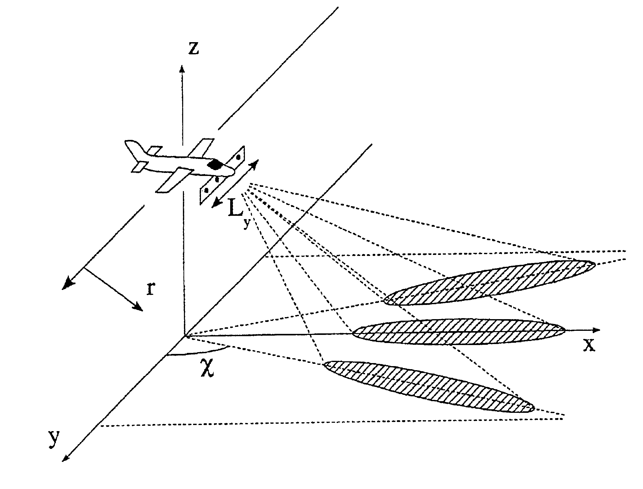
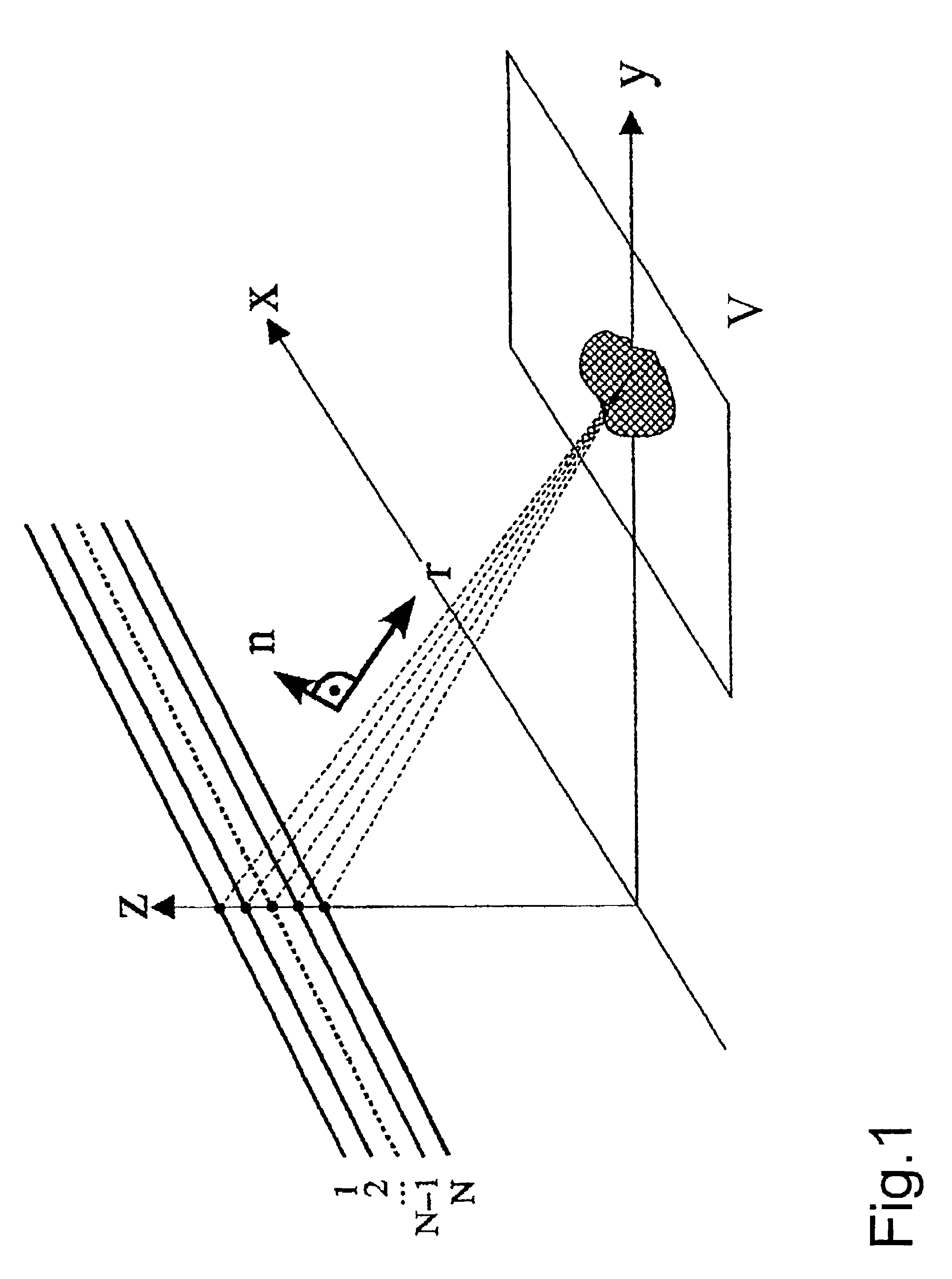
[0036]Referring now to FIG. 1 there is illustrated in a Cartesian x-y-z-system of coordinates the basic geometry of a radar sensor in a side view for three-dimensional object imaging. The movement of the sensors is to be imagined parallel along the x axis. The various independent antenna elements of an antenna array are arranged so that each thereof (paths 1,2 . . . N-1, N of the antenna elements) views the scene and thus the volume targets V at a different angle.

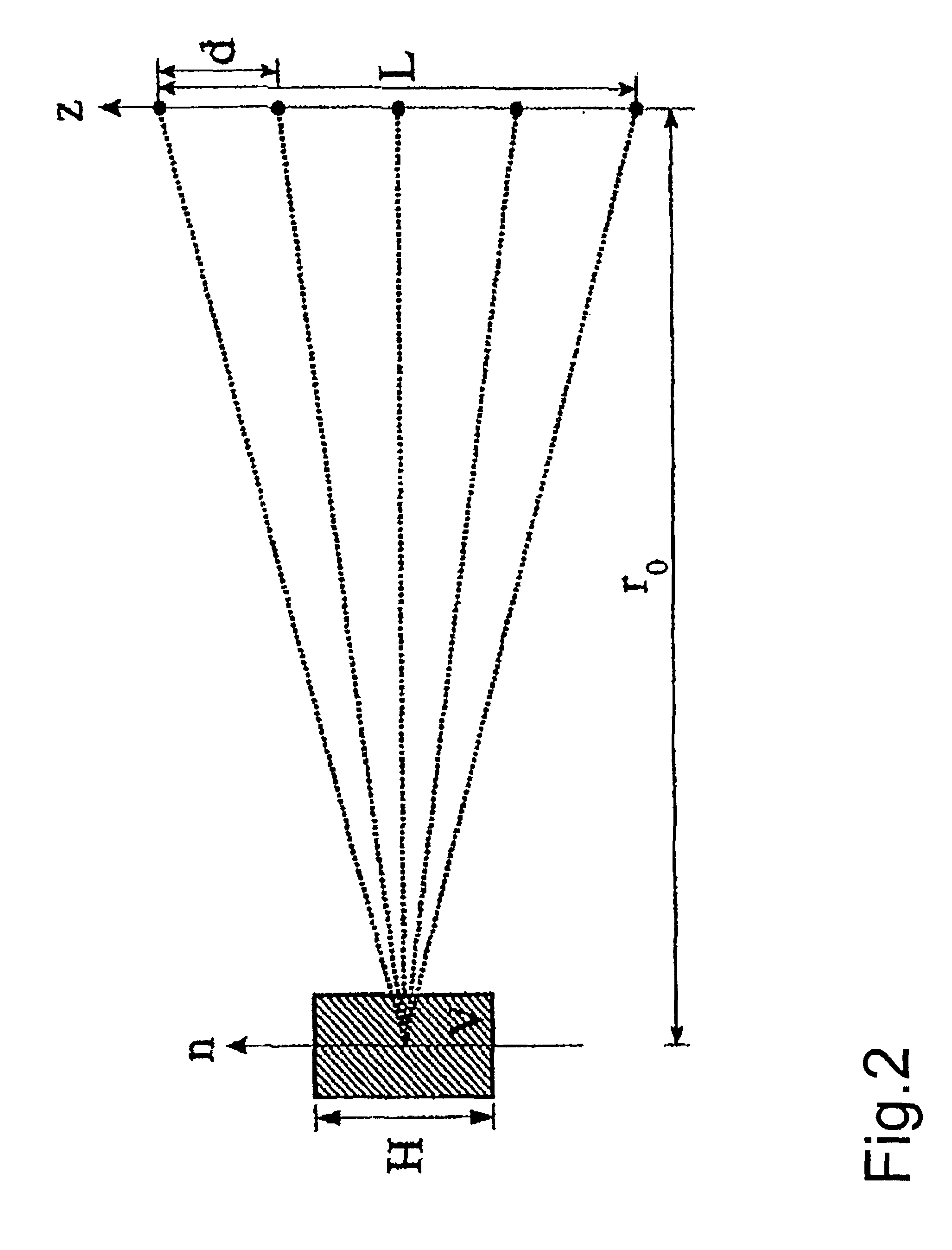
[0037]Referring now to FIG. 2 there is illustrated a simplified geometry in which an array of antenna elements has the aperture length L and the center-spacing of the antenna elements is d and the mean angle of incidence is 0°, i.e. the n axis as shown in FIG. 1 is parallel to the z direction. In this geometry the spacing between a scatter at the elevation n0 and the antenna element at the position z is r⁢ ⁢(z,n0)=2⁢r02+(z-n0)2≈2⁢r0+(z-n0)2r0(1)

[0038]The signal sr(z, n0) received by this antenna element can thus be modeled ...


PUM


Abstract

By means of tomograhic radar technique consisting of a coherent combination of large numbers of synthetic aperture radar images acquired by several air or space SAR systems having different look angles, a real three-dimensional imaging of volume scatterers is achieved. This allows the separation of the backscattered signal of volume scatterers in the height direction which can be further evaluated independently. The invention can be put to use in the three-dimensional analysis of vegetation layers and ground strata, but also for imaging and mapping of buildings, urban areas and mountainous terrain.

Description

FIELD OF THE INVENTION[0001]The invention relates to a tomographic synthetic aperture radar (SAR) method operating with an airborne or spaceborne radar sensor for three-dimensional object imaging in which a true three-dimensional image is obtained by coherent combination of a plurality of SAR sensor images obtained at differing viewing angles. The backscatter contributions of volume targets are separated in elevation and can be analyzed each independent of the other.BACKGROUND[0002]Imaging radar methods operate with an active radar sensor which, by means of radiating and receiving electromagnetic waves in the microwave range, generates a reflectivity map of the illuminated area. In recent years synthetic aperture radar (SAR) has attained major significance in remote sensing due to the high resolution and rich information content of SAR images. In addition to traditional applications in geography and in topographical and thematic mapping, SAR sensors also find application nowadays in...

Claims


Application Information

Patent Timeline
IPC IPC(8): G01S13/00G01S13/90
CPCG01S13/9035G01S2013/9058G01S13/904G01S13/9043G01S13/9058
Inventor MOREIRA, ALBERTOREIGBER, ANDREAS
Owner DEUTSCHES ZENTRUM FUER LUFT & RAUMFAHRT EV
Why Eureka
Try Eureka