Position estimation

a technology of position estimation and position estimation, applied in direction finders, direction finders using radio waves, instruments, etc., can solve the problems of large errors in certain situations, difficult task of estimating the position of receivers, and problems not only for gps receivers

Inactive Publication Date: 2005-05-17
NOKIA SOLUTIONS & NETWORKS OY
View PDF3 Cites 50 Cited by
  • Summary
  • Abstract
  • Description
  • Claims
  • Application Information

AI Technical Summary

Benefits of technology

[0020]It is an advantage of the invention that it allows to exploit the available information optimally. It allows in particular to estimate a reliable position of a receiver even if the number of available beacons is less than the minimum number required in conventional methods.
[0021]Initial information on the receiver position is available in many cases in form of a reference position. A reference position may be the position of a nearby base station of a mobile communication network or of another beacon. It may also be estimated from previous position fixes of the receiver.
[0022]The error criterion which is minimized may be for example the maximum possible error, the mean absolute error or the mean square error which results at a respectively selected position.
[0023]The invention can be implemented in particular, though not exclusively, in software.
[0024]The invention can be employed for the positioning of any type of ranging receiver receiving code modulated signals from any type of beacons, for instance for a receiver of a positioning system like GPS or Galileo receiving code modulated signals from satellites.
[0025]Other objects and features of the present invention will become apparent from the following detailed description considered in conjunction with the accompanying drawings. It is to be understood, however, that the drawings are designed solely for purposes of illustration and not as a definition of the limits of the invention, for which reference should be made to the appended claims. It should be further understood that the drawings are not drawn to scale and that they are merely intended to conceptually illustrate the structures and procedures described herein.

Problems solved by technology

Thus, it is a challenging task to estimate the position of a receiver based on incomplete information.
Such a freezing of coordinates may lead to large errors in certain situations, though.
It is to be understood that the problem arises not only for GPS receivers, but as well with any other type of ranging receivers for which the position is to be calculated based on code modulated beacon signals.

Method used


Image

  • Position estimation
  • Position estimation
  • Position estimation

Examples


Embodiment Construction

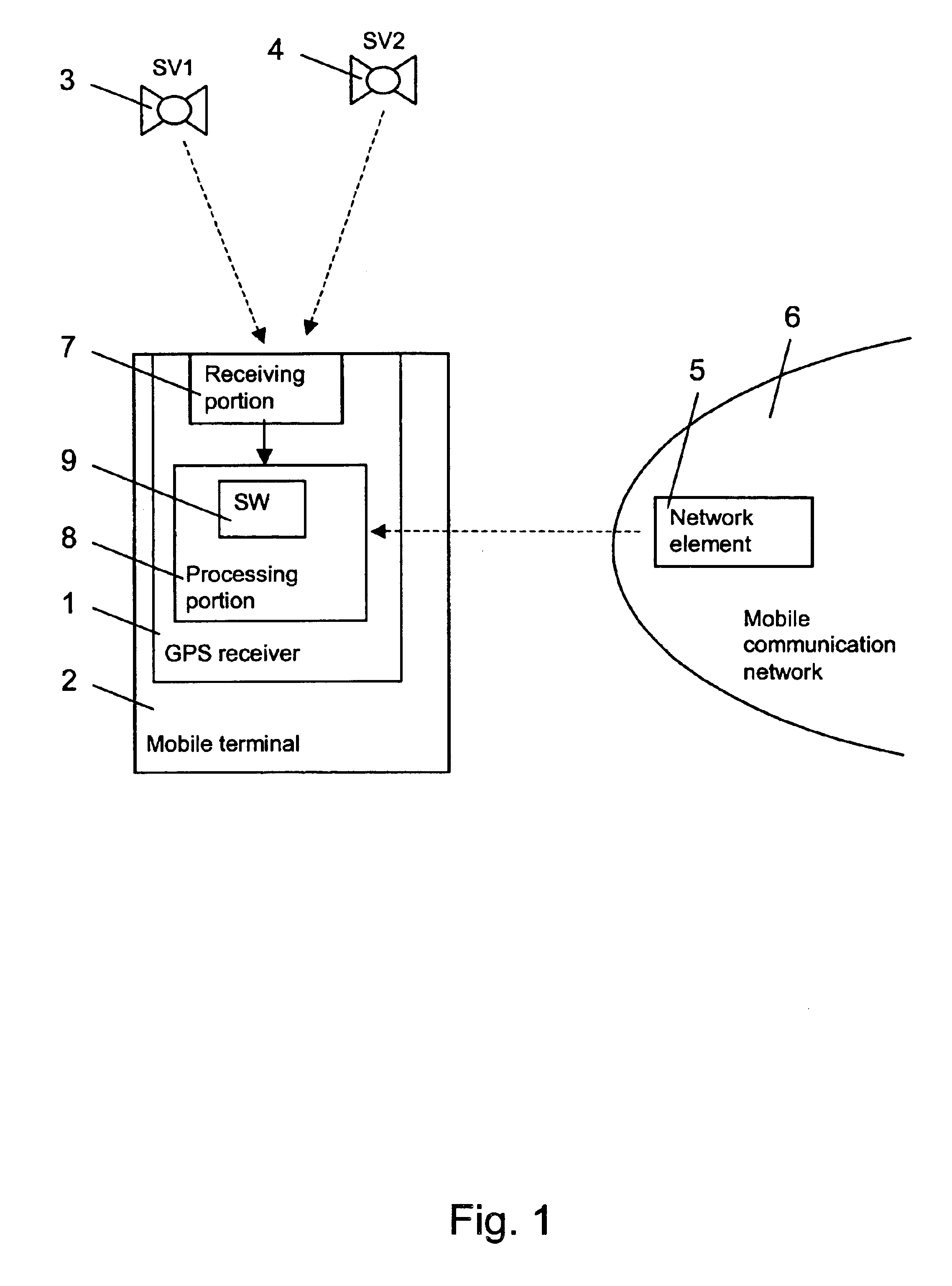
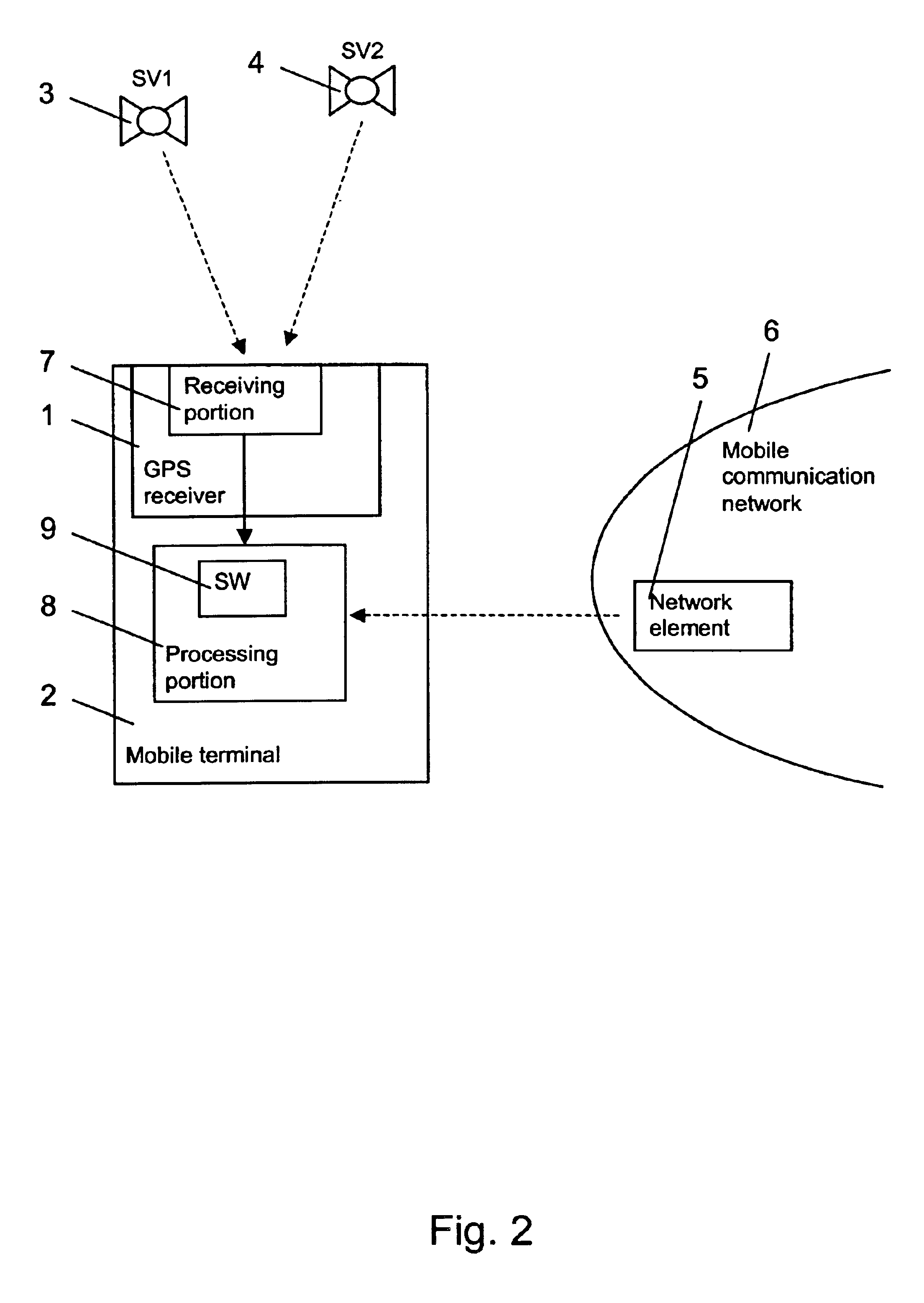
[0034]FIG. 1 schematically presents by way of example a GPS positioning system, in which the position of a GPS receiver 1 can be determined in accordance with the invention.

[0035]The positioning system comprises a mobile terminal 2 with the GPS receiver 1, a plurality of GPS satellites, of which two are shown as SV1 3 and SV2 4, and a network element 5 of a mobile communication network 6.

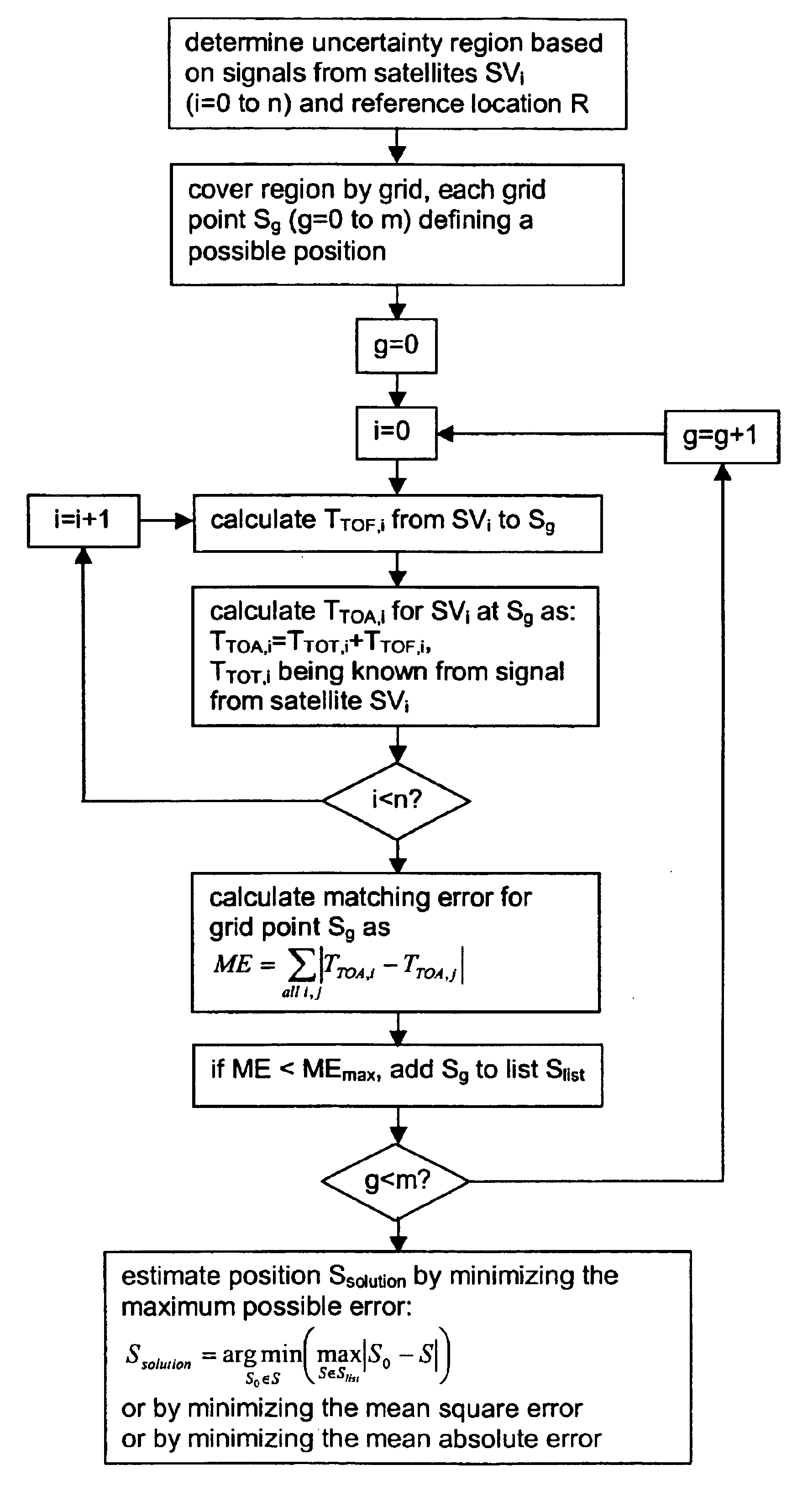
[0036]The GPS receiver 1 includes a receiving portion 7 and a processing portion 8. The receiving portion 7 receives, acquires and tracks code modulated signals transmitted by the GPS satellites 3, 4. Further, it performs measurements on the signals and extracts information included in the signals. The processing portion 8 uses a software 9 for estimating the position of the GPS receiver 1 based on information received from the receiving portion 7. For estimating the receiver position, the processing portion 8 first determines a region which can be assumed to comprise the receiver positions and then...


PUM


Abstract

The invention relates to a method for estimating the position of a receiver receiving code modulated signals from at least one beacon. The method comprises delimiting a region containing the receiver position based on a code modulated signal received at the receiver from at least one beacon and on available information including at least an initial information on the receiver position. The method further comprises estimating the receiver position as a position within the delimited region which minimizes an error criterion. The invention relates equally to such a receiver, to a system comprising such a receiver and to a corresponding software program product enabling an estimation of the position of a receiver.

Description

FIELD OF THE INVENTION[0001]The invention relates to a method for estimating the position of a receiver receiving code modulated signals from at least one beacon. The invention relates equally to such a receiver, to a system comprising such a receiver and to a software program product in which a software code for estimating the position of a receiver receiving code modulated signals from at least one beacon is stored.BACKGROUND OF THE INVENTION[0002]It is known in the state of the art to determine the position of a receiver based on code modulated signals from several beacons using, for example, a CDMA (Code Division Multiple Access) spread spectrum communication.[0003]For a spread spectrum communication in its basic form, a data sequence is used by a transmitting unit to modulate a sinusoidal carrier and then the bandwidth of the resulting signal is spread to a much larger value. For spreading the bandwidth, the single-frequency carrier can be multiplied for example by a high-rate ...

Claims


Application Information

Patent Timeline
Patent Type & Authority Patents(United States)
IPC IPC(8): G01S1/00G01S1/08G01S3/02H04B7/185G01S5/14G01S19/11
CPCG01S19/50G01S19/25
Inventor AKOPIAN, DAVIDVALIO, HARRISYRJARINNE, JARI
Owner NOKIA SOLUTIONS & NETWORKS OY
Why Eureka
Try Eureka