Objective with pupil obscuration

a technology of objective and pupil, applied in the field of objective with mirror, can solve the problems of greater aperture obscuration, mirror obscuration, more unfavorable ratio of mirror aperture diameter to mirror diameter, etc., and achieve the effect of reducing aperture obscuration and improving projecting objectives

Inactive Publication Date: 2005-05-17
CARL ZEISS SMT GMBH
View PDF16 Cites 120 Cited by
  • Summary
  • Abstract
  • Description
  • Claims
  • Application Information

AI Technical Summary

Benefits of technology

[0014]The first partial objective, which comprises a first convex mirror with a first central mirror aperture and a second concave mirror with a second central mirror aperture, projects a first field plane onto an intermediate image. Light rays which emanate from the first field plane first pass through the second mirror aperture, are then reflected at the first mirror, next reflected at the second mirror, and then pass through the first mirror aperture. Since the diameter of the second mirror aperture is decisively determined by the diameter of the first mirror, it is advantageous for the purpose of reducing the aperture obscuration to provide the first mirror as convex mirror and the second mirror as concave mirror so that the first mirror has a substantially lesser diameter than the second mirror.
[0024]Due to the negative optical power of the first mirror, it is possible to make the diameter of the second mirror substantially larger than the diameter of the first mirror. The ratio of the diameter of the second mirror to the diameter of the first mirror should be greater than 3:1, in particular greater than 5:1. Since the diameter of the mirror aperture of the second mirror is approximately equal to the diameter of the first mirror, the second mirror leads only to a low aperture obscuration, or to no increase in the aperture obscuration, which is caused by the other mirrors.
[0037]To use the objective as a projection objective or as an inspection objective, it is advantageous if the axial distance of the first field plane from the second field plane is at most 3000 mm.
[0045]In the fabrication of a single layer of a micro-structured semiconductor component, the positions of the micromirrors are controlled in accordance with a prescribed pattern in such a way that only the ray pencils of those micromirrors which are to be projected are aimed into the entrance pupil of the objective. All other ray pencils are prevented from contributing to the projection by a suitable ray trap.

Problems solved by technology

This leads to a greater aperture obscuration when the free image-side working distance and the substrate thickness of the convex mirror are considered.
However, in the case of a lesser mirror diameter, the mirror obscuration, that is to say the ratio of the diameter of the mirror aperture to the diameter of the mirror, is more unfavorable.
This leads to a very high aperture obscuration by the convex mirror.
Because of the use of lenses, it is not possible to use this objective in the case of EUV wavelengths (<20 nm).

Method used


Image

  • Objective with pupil obscuration
  • Objective with pupil obscuration
  • Objective with pupil obscuration

Examples


Embodiment Construction

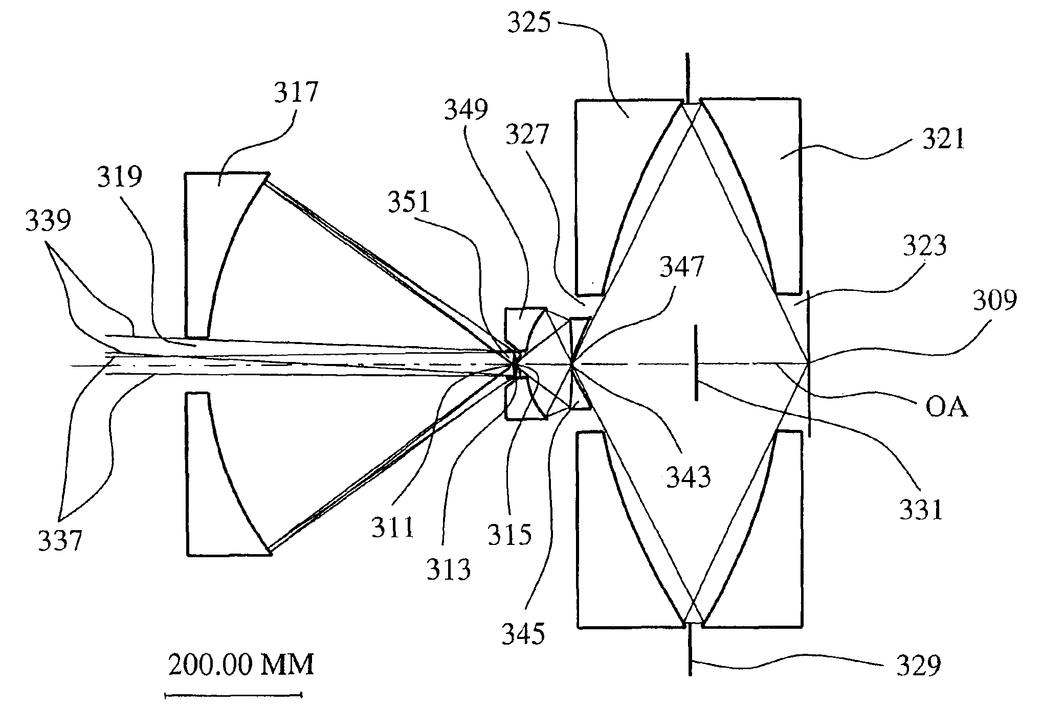
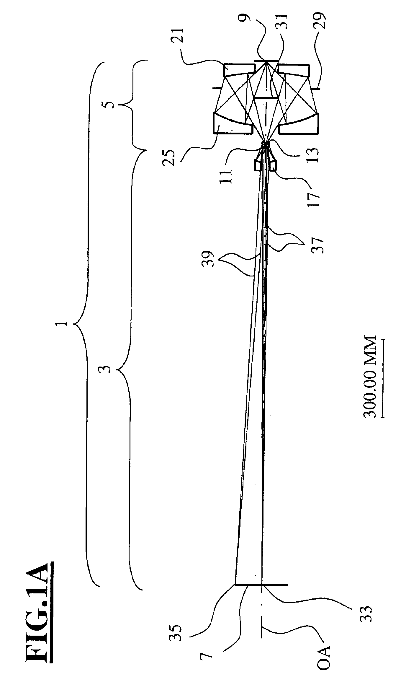
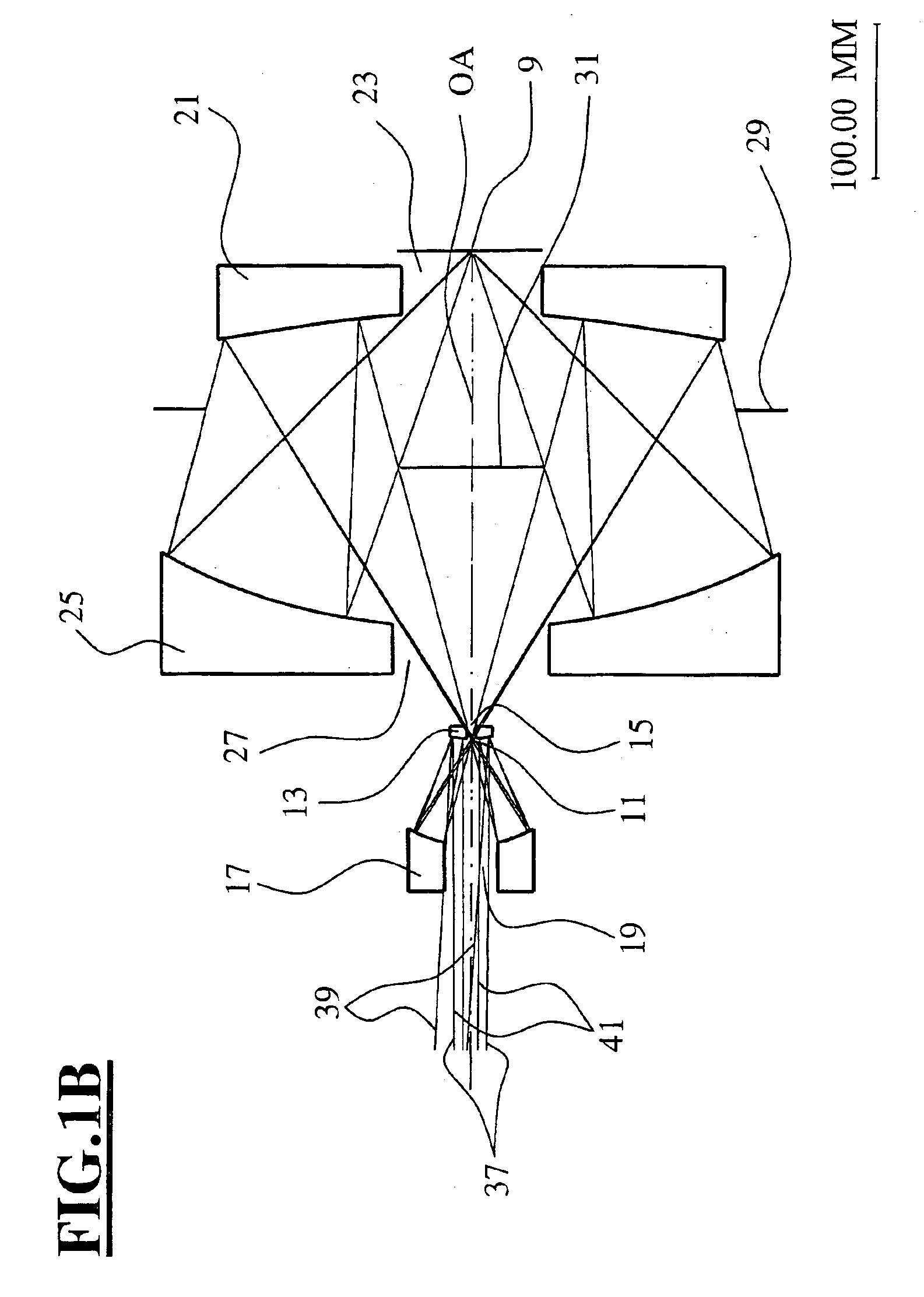
[0018]Only light rays with aperture angles starting from a specific minimum value contribute to the projection in this objective with pupil obscuration. The aperture angles are measured with reference to the optical axis. The minimum aperture angle results for the light ray which is still transmitted by all mirrors and not vignetted by a mirror aperture. The light rays are not directly vignetted by the mirror apertures, but pass as false light through the latter and strike a special light blocking device, while the remaining rays of a ray pencil with larger aperture angles are reflected by the mirrors. The aperture obscuration is defined as the ratio of the sine of the minimum aperture angle in the second field plane to the numerical aperture in the second field plane. Values of less than 0.6, in particular less than 0.5, can be achieved for the aperture obscuration by means of the arrangement of the intermediate image in the vicinity of the first mirror, and with the use of a conca...


PUM

PropertyMeasurementUnit
diameteraaaaaaaaaa
axial distanceaaaaaaaaaa
wavelengthsaaaaaaaaaa

Abstract

An objective is configured with a first partial objective and a second partial objective. The first partial objective, which projects a first field plane onto an intermediate image, has a first, convex mirror and a second, concave mirror. The second partial objective, which projects the intermediate image onto a second field plane, has a third and a fourth mirror, both concave. All of the four mirrors have central mirror apertures. The axial distance between the first and second mirrors is in a ratio between 0.95 and 1.05 relative to the distance between the second mirror and the intermediate image. The axial distance ZM3-IM between the third mirror and the second field plane conforms to the relationship 0.03·DuM3+5.0⁢ ⁢mm<ZM3-IM<0.25·DuM3tan⁡(arcsin⁡(NA)).NA represents the numerical aperture NA in the second field plane, and DuM3 represents the diameter of the third mirror. The objective furthermore has a Petzval radius with an absolute value larger than the distance between the first and second field planes.

Description

CROSS REFERENCE TO RELATED APPLICATIONS[0001]This application is a continuation of International Application Serial No. PCT / EP02 / 09153, filed Aug. 16, 2002 and published in English on Feb. 27, 2003, which is still pending, and which claims priority from German Patent Application No. 101 39 177.3, filed Aug. 16, 2001, all of which are hereby incorporated by reference in their entirety.BACKGROUND OF THE INVENTION[0002]The invention relates to an objective with mirrors whose central mirror apertures cause a pupil obscuration. An objective of the type considered herein comprises two partial objectives, the first partial objective projecting a first field plane onto an intermediate image, and the second partial objective projecting the intermediate image onto a second field plane. Such objectives are used, for example, as projection objectives in microlithography or as inspection objectives for observing surfaces, in particular wafer surfaces.[0003]Catoptric reduction objectives with a p...

Claims


Application Information

Patent Timeline
Patent Type & Authority Patents(United States)
IPC IPC(8): G02B17/08G02B13/14G02B13/18G02B17/00G02B13/24G02B17/06G03F7/20H01L21/027
CPCG02B17/0652G03F7/70291G03F7/70233G03F7/70225
Inventor MANN, HANS-JURGENULRICH, WILHELM
Owner CARL ZEISS SMT GMBH
Why Eureka
Try Eureka