Recording apparatus having improved anti-vibration arrangements

a recording apparatus and anti-vibration technology, applied in the direction of casings/cabinets/drawers, casings/cabinets/drawers, instruments, etc., can solve the problems of reducing pitch, deteriorating reading/writing accuracy, and no shroud, so as to reduce flutter vibration, facilitate manufacturing, and reduce the effect of air flow and disturbance of air flow

Inactive Publication Date: 2005-05-17
HITACHI GLOBAL STORAGE TECH JAPAN LTD
View PDF8 Cites 11 Cited by
  • Summary
  • Abstract
  • Description
  • Claims
  • Application Information

AI Technical Summary

Benefits of technology

[0007]However, in the first method (method of reducing the size of the gap between shrouds), the magnetic disk apparatus needs to have an arm with a head placed at the end inserted on the disk surface and no shroud can be provided over the range in which the arm traverses on the disk surface. Therefore, reducing the gap between the shroud and disk limits the effect of reducing cyclic secondary flow due to input / output of an air flow on the upper side and under side of the disk. Moreover, even if a cyclic secondary flow on the upper side and under side of the disk can be suppressed, the circumferential air flow is not suppressed, and therefore it is not possible to reduce flutter vibration caused by disturbance that occurs when the flow in the disk circumferential direction hits the arm, etc. For these reasons, the flutter vibration reducing effect is limited.
[0023]Such a configuration can facilitate manufacturing, reduce the air flow and disturbance of the air flow simultaneously and can thereby reduce flutter vibration effectively.

Problems solved by technology

However, flutter vibration is approximately proportional to the square of the disk rotational speed, the reading / writing accuracy deteriorates due to flutter vibration as described above, which prevents the track pitch from being reduced.
However, in the first method (method of reducing the size of the gap between shrouds), the magnetic disk apparatus needs to have an arm with a head placed at the end inserted on the disk surface and no shroud can be provided over the range in which the arm traverses on the disk surface.
Therefore, reducing the gap between the shroud and disk limits the effect of reducing cyclic secondary flow due to input / output of an air flow on the upper side and under side of the disk.
Moreover, even if a cyclic secondary flow on the upper side and under side of the disk can be suppressed, the circumferential air flow is not suppressed, and therefore it is not possible to reduce flutter vibration caused by disturbance that occurs when the flow in the disk circumferential direction hits the arm, etc.
For these reasons, the flutter vibration reducing effect is limited.
On the other hand, the second method (method of placing or fixing a squeeze air bearing plate facing the disk surface with a gap of 0.3 mm or less in between) forcibly reduces disk vibration by a squeeze attenuating force, but in order to achieve the squeeze effect, it is necessary to place or fix a squeeze air bearing plate with extremely high dimensional accuracy to place / fix it with a gap of 0.3 mm or less, requiring an enormous effort from the standpoint of working accuracy, ease of assembly and shock resistance.
Furthermore, according to the third method (method of adopting a two-stage structure of projections and depressions of a cover of a magnetic disk and narrowing as much as possible the gap between the disk and cover corresponding to the area outside the area where the arm on the magnetic disk surface traverses compared to the area where the arm traverses), narrowing the gap produces a large height difference in the gap between the disk and cover on the boundary between the area where the arm transverses and the other area.
Thus, even if the air flow between the disk and cover can be controlled, this height difference produces large disturbance of air flow, resulting in a problem that even if the gap is narrowed, the height difference increases and it is not possible to reduce flutter vibration.

Method used


Image

  • Recording apparatus having improved anti-vibration arrangements
  • Recording apparatus having improved anti-vibration arrangements
  • Recording apparatus having improved anti-vibration arrangements

Examples


second embodiment

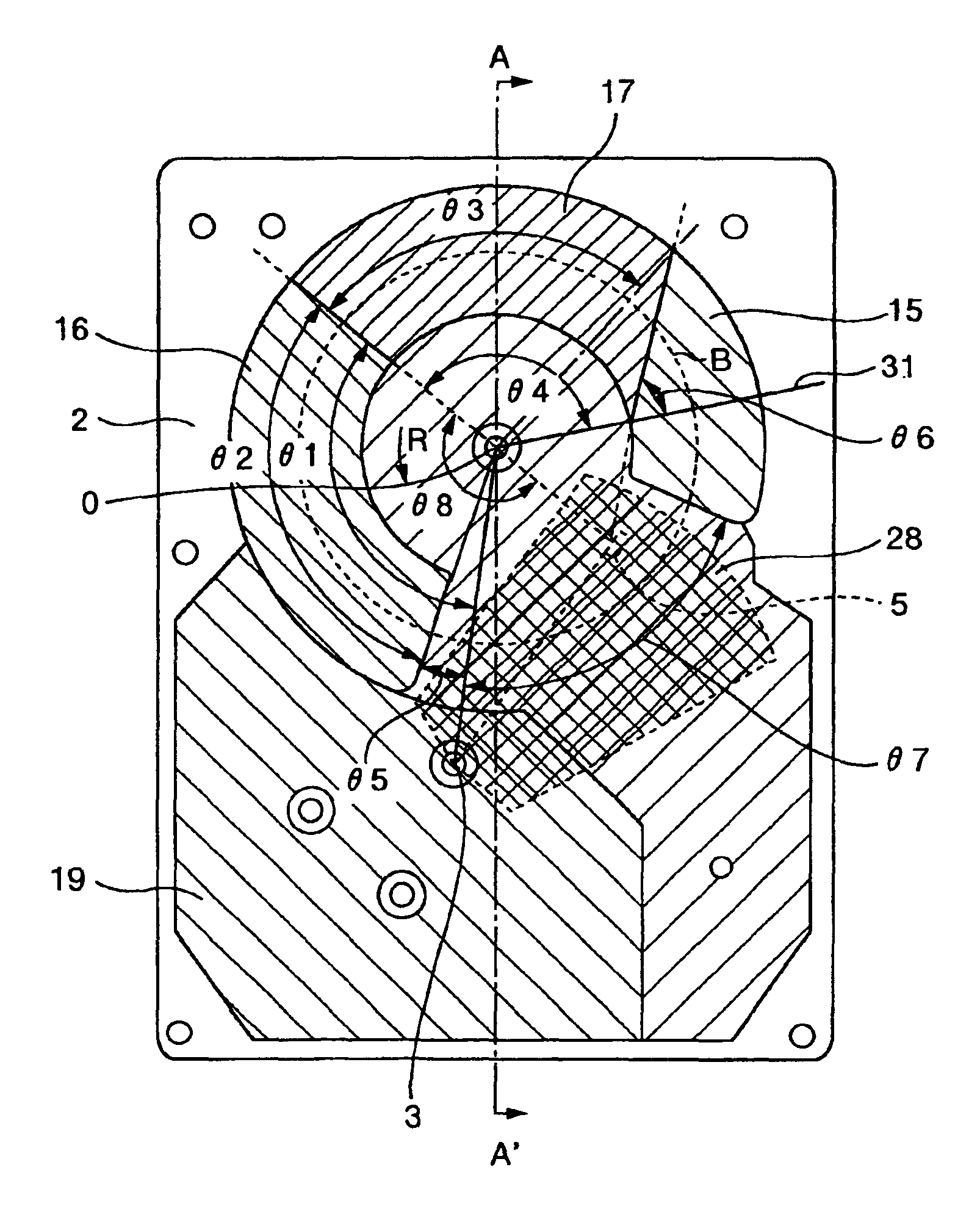
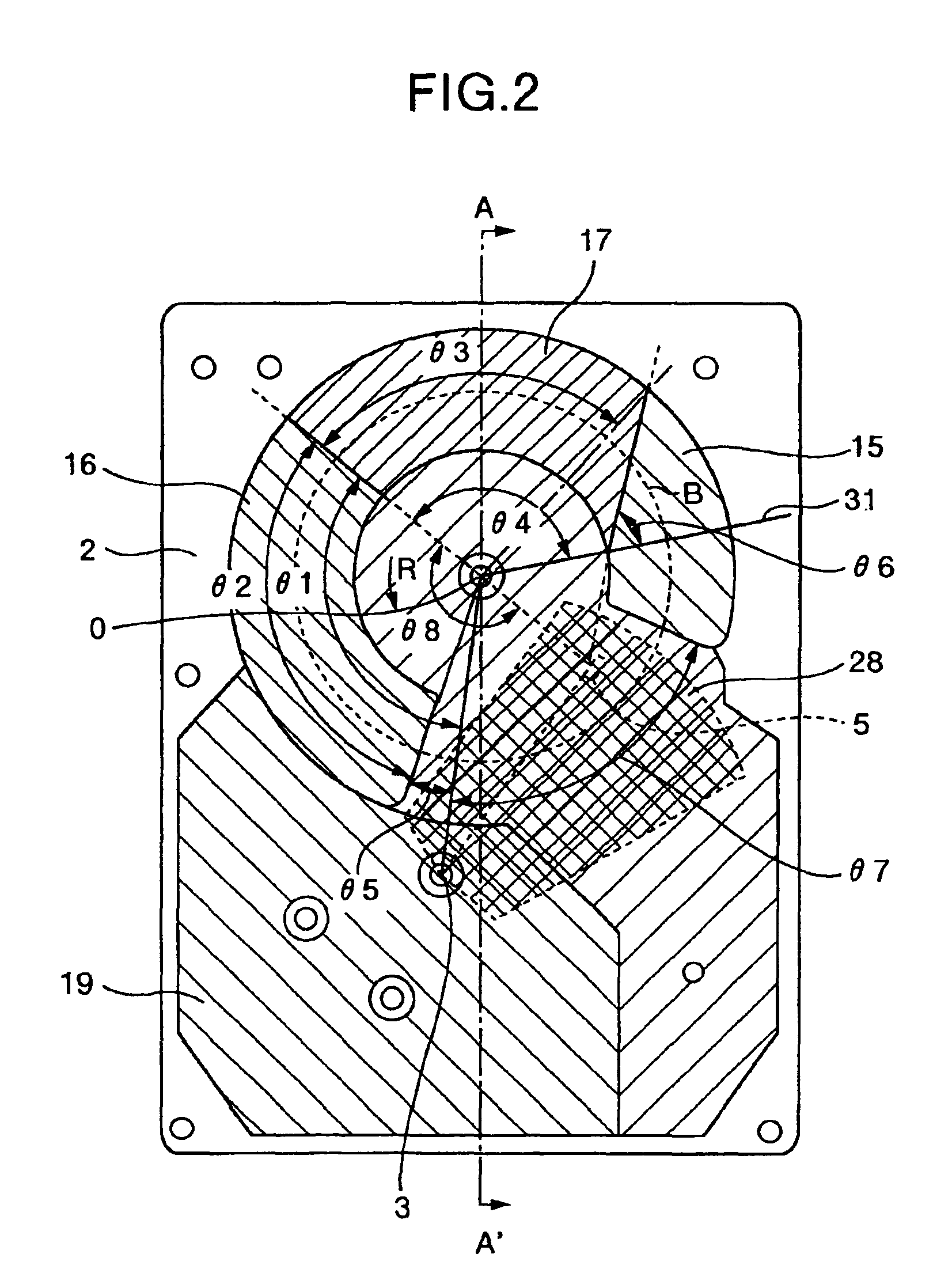
[0072]Likewise, a configuration and effects of a recording apparatus according to the present invention will be explained using FIG. 4.

[0073]In the configuration shown in FIG. 2, the first convex sections 15 and 16 are provided on both sides of the second convex section 17 in the rotational direction of the disk in addition to the second convex section 17. However, as shown with single-dot dashed line in FIG. 4, the first convex sections 15A and 16A may also be included together with the range 28 by a single convex section having the same height H3 as the hight of the range 28 where the arm traverses. That is, the single convex section 17 may also be formed for the range 28 in which the arm traverses.

[0074]At this case, with regard to the position of the convex section 17, it is also possible to reduce the flutter amplitude from the standard by setting θ1 at 110° to 170° and minimize the flutter amplitude (flutter amplitude ratio=0.85) by setting θ1 at 140° regardless of the fan sha...

third embodiment

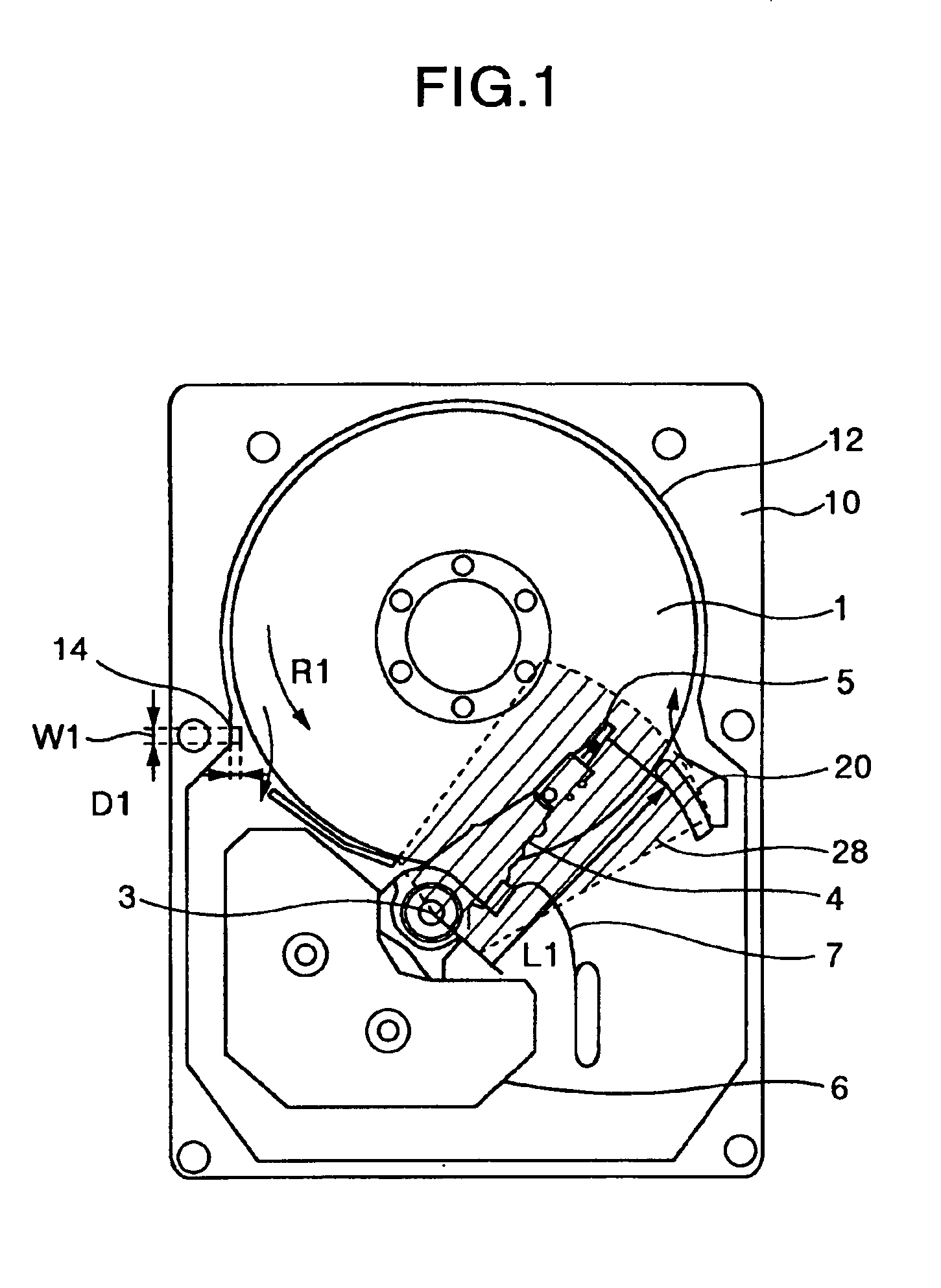
[0076]Then, a configuration and effects of a recording apparatus according to the present invention will be explained using FIG. 1 and FIG. 9 to FIG. 12.

[0077]FIG. 9 is an enlarged plan view of main parts of a recording apparatus according to the third embodiment of the present invention. FIG. 10 and FIG. 11 illustrate an air flow at the opening of a shroud. FIG. 12 illustrates an experiment result. The same reference numerals in FIG. 9 to FIG. 11 as those in FIG. 1 denote the same parts.

[0078]As shown in FIG. 1, In this embodiment, a protrusion 14 is formed on the arc opening of the shroud 12 at the upstream side relative to the arm. The protrusion 14 has a thickness D1 of about 1 mm, a width W1 of about 1 to 2 mm and extends over the entire internal height of the housing or in at least a part thereof in the direction of the disk rotation axis, that is, in the direction perpendicular to the drawing sheet. The enlarged view of the protrusion 14 is as shown in FIG. 9.

[0079]FIG. 10 sh...


PUM

PropertyMeasurementUnit
radiusaaaaaaaaaa
lengthaaaaaaaaaa
lengthaaaaaaaaaa

Abstract

In a recording apparatus capable of reducing an airflow and disturbance of the air flow simultaneously, thereby reducing flutter vibration effectively, a cover includes first convex sections for reducing a size of a gap between a disk surface and a cover or between the disk surface arid a housing in an area outside of an area in which an arm traverses on a disk in comparison with the area in which the arm traverses, and a second convex section on a part of the first convex sections to further reduce the size of the gap, and the second convex section is provided in a range extending with a tan shape thereof in a reverse rotational direction of said disk from a position distant by 110-170° in the reverse rotational direction from a straight line connecting the rotational shaft of said disk and the rotational shaft of said arm.

Description

BACKGROUND OF THE INVENTION AND RELATED ART STATEMENT[0001]The present invention relates to a recording apparatus such as a magnetic disk apparatus or the like, in which a rotary disk-shaped recording medium is used, and more particularly, to a recording apparatus having a structure for reducing vibration of the recording medium caused by rotation.[0002]A conventional recording apparatus, for example, a magnetic disk apparatus is generally constructed of a rotary disk-shaped recording medium, an arm provided with a head to read / write from / to this recording medium placed at the end, an actuator to move the head to a predetermined position, a housing to house these components, a control apparatus and an input / output system. It is known of a magnetic disk apparatus that an air flow is created inside the casing by a rotating disk and vibration of the disk called “flutter” occurs due to disturbance of the air flow. When the disk vibrates, the relative positions of the disk and head chang...

Claims


Application Information

Patent Timeline
Patent Type & Authority Patents(United States)
IPC IPC(8): G11B33/08G11B33/14G11B5/60G11B25/04
CPCG11B5/6005G11B33/142G11B33/08G11B5/012
Inventor NISHIJIMA, NORIYOKOUNO, TAKASHIKOBAYASHI, ISAOIZUMIDA, HIDEKIEGUCHI, TAKEHIKO
Owner HITACHI GLOBAL STORAGE TECH JAPAN LTD
Why Eureka
Try Eureka